AdonisFX Sensors are nodes in charge of interpreting data extracted from transform nodes and compute information that can be fed into the deformers to alter their behavior. Sensors work in combination with Locators to display the computed information in an intuitive way using coloring. The sensors produce the results in two separated outputs: the raw value result of the evaluation of the input transform nodes (e.g. Out Angle); and the remapped value result of the evaluation of the raw value into the existing remap ramp attributes (e.g. Out Angle Remap). Thanks to this, the remapped values are already adjusted within a custom range of activation that will drive the coloring of the locators and the activation of an AdnMuscle for example.
AdnSensorPosition is the sensor for computing meaningful output raw values representing the velocity or acceleration of a transform node. Additionally, the sensor remaps the values of velocity and acceleration to produce desirable activation values within a certain range to drive the simulation of an AdonisFX deformer. This sensor has to work in combination with an AdnLocatorPosition both for setup and visualization. An example use case for this sensor would be applying it to the wrist connection of an arm outputting velocities while swinging.
An AdnSensorPosition will be in charge of computing, remapping and feeding activation (or other) values into the AdnLocatorPosition for visualization purposes, which in turn feeds the AdonisFX deformers to drive the simulation. The value of the sensor can be used, for example, to drive the activation of a muscle simulating contraction to increase its stiffness.
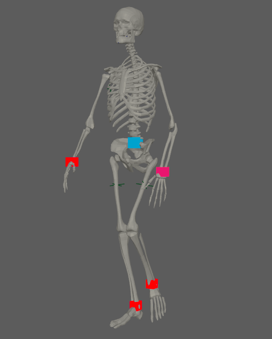
Figure 1: AdnSensorPosition used in a human model.
There are two different methods of creating an AdnSensorPosition, depending if it is to be applied on an existing AdnLocatorPosition or creating it alongside the sensor.
If applying to an already existing AdnLocatorPosition:
Select an AdnLocatorPosition from your scene.
Press the button in the AdonisFX shelf or press Position in the AdonisFX menu, under the Sensor submenu. If the shelf button is double-clicked or the option box in the menu is selected a window will be displayed where a custom name and initial attribute values can be set.
The AdnSensorPosition is created, applied to the selected AdnLocatorPosition.
If creating the locator alongside the sensor:
Select a transform node in the scene.
Press the button in the AdonisFX shelf or press Position in the AdonisFX menu, under the Sensor submenu. If the shelf button is double-clicked or the option box in the menu is selected a window will be displayed where a custom name and initial attribute values can be set.
The AdnSensorPosition is created, alongside a new AdnLocatorPosition applied to the same transform node.
Figure 2: AdnSensorPosition and AdnLocatorPosition in the node graph .
Position in world space of the transform node. This plug is used if: 1) it has input connections; 2) it does not have input connections and Position Matrix does not have input connections neither. Otherwise, Position Matrix is used instead.
Position Matrix
Matrix
Identity
✓
Matrix containing the position in world space of the transform node. This plug is used if: 1) it has input connections and Position does not have input connections. Otherwise, Position is used instead.
Output
Name
Type
Default
Animatable
Description
Out Velocity
Float
0.0
✗
Magnitude of the velocity of the transform node. It is the raw value calculated before the remapping.
Out Acceleration
Float
0.0
✗
Magnitude of the acceleration of the transform node. It is the raw value calculated before the remapping.
Remapped Output
Name
Type
Default
Animatable
Description
Out Velocity Remap
Float
0.0
✗
Output remapped velocity. It is the result of remapping the Out Velocity.
Out Acceleration Remap
Float
0.0
✗
Output remapped acceleration. It is the result of remapping the Out Acceleration.
Velocity Remap Settings
Name
Type
Default
Animatable
Description
Selected Position
Float
0.0
✓
X-axis value of the ramp attribute.
Selected Value
Float
0.0
✓
Y-axis value of the ramp attribute.
Interpolation
Enumerator
Linear
✓
Interpolation method to be used between every two consecutive points in the ramp. There are four options: None, Linear, Smooth and Spline.
Input Min Velocity
Float
0.0
✓
Lower limit of the range used to map the Out Velocity value before evaluating it on the ramp attribute.
Input Max Velocity
Float
10.0
✓
Upper limit of the range used to map the Out Velocity value before evaluating it on the ramp attribute.
Output Min Velocity
Float
0.0
✓
Lower limit of the range used to map the value returned by the ramp attribute and calculate the final remapped velocity.
Output Max Velocity
Float
1.0
✓
Upper limit of the range used to map the value returned by the ramp attribute and calculate the final remapped velocity.
Acceleration Remap Settings
Name
Type
Default
Animatable
Description
Selected Position
Float
0.0
✓
X-axis value of the ramp attribute.
Selected Value
Float
0.0
✓
Y-axis value of the ramp attribute.
Interpolation
Enumerator
Linear
✓
Interpolation method to be used between every two consecutive points in the ramp. There are four options: None, Linear, Smooth and Spline.
Input Min Acceleration
Float
-10.0
✓
Lower limit of the range used to map the Out Acceleration value before evaluating it on the ramp attribute.
Input Max Acceleration
Float
10.0
✓
Upper limit of the range used to map the Out Acceleration value before evaluating it on the ramp attribute.
Output Min Acceleration
Float
0.0
✓
Lower limit of the range used to map the value returned by the ramp attribute and calculate the final remapped acceleration.
Output Max Acceleration
Float
1.0
✓
Upper limit of the range used to map the value returned by the ramp attribute and calculate the final remapped acceleration.
Time Attributes
Name
Type
Default
Animatable
Description
Start Time
Time
Current frame
✗
Determines the frame at which the playback/simulation starts.
Current Time
Time
Current frame
✓
Current playback frame.
Scale Attributes
Name
Type
Default
Animatable
Description
Time Scale
Float
1.0
✓
Sets the scaling factor applied to the compute the velocity or acceleration. Has a range of [0.001, 10.0]. The upper limit is soft, higher values can be used.
Space Scale
Float
1.0
✓
Sets the scaling factor applied to velocity or acceleration. Has a range of [0.001, 100.0]. The upper limit is soft, higher values can be used.
AdnSensorDistance is the sensor for computing meaningful output raw values representing the distance, velocity or acceleration between two transform nodes. Additionally, the sensor remaps the values of distance, velocity and acceleration to produce desirable activation values within a certain range to drive the simulation of an AdonisFX deformer. This sensor has to work in combination with an AdnLocatorDistance both for setup and visualization. An example use case for this sensor would be applying it to the connection made between bones which would compute the distance between two bones moving together.
An AdnSensorDistance will be in charge of computing, remapping and feeding activation (or other) values into the AdnLocatorDistance for visualization purposes, which in turn feeds the AdonisFX deformers to drive the simulation. The value of the sensor can be used, for example, to drive the activation of a muscle simulating contraction to increase its stiffness.
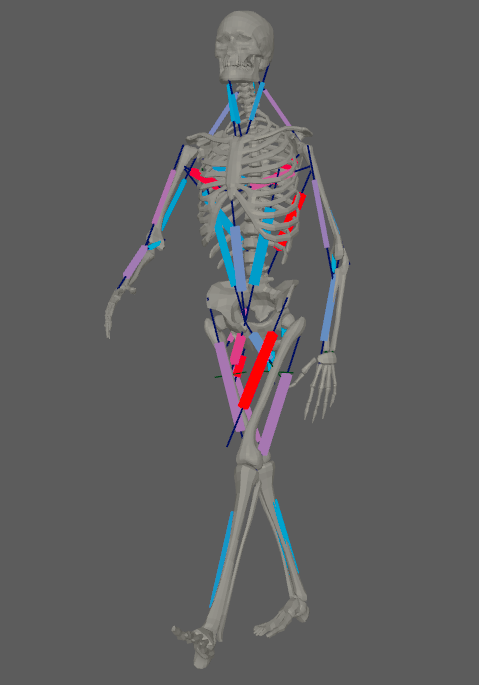
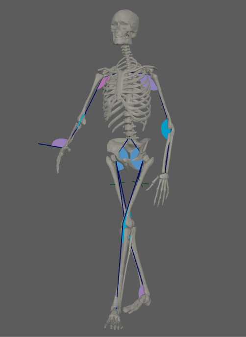
Figure 3: AdnSensorDistance used in a human model.
There are two different methods of creating an AdnSensorDistance, depending if it is to be applied on an existing AdnLocatorDistance or creating it alongside the sensor.
If applying to an already existing AdnLocatorDistance:
Select an AdnLocatorDistance from your scene.
Press the button in the AdonisFX shelf or press Distance in the AdonisFX menu, under the Sensor submenu. If the shelf button is double-clicked or the option box in the menu is selected a window will be displayed where a custom name and initial attribute values can be set.
The AdnSensorDistance is created, applied to the selected AdnLocatorDistance.
If creating the locator alongside the sensor:
Select two transform nodes in the scene.
Press the button in the AdonisFX shelf or press Distance in the AdonisFX menu, under the Sensor submenu. If the shelf button is double-clicked or the option box in the menu is selected a window will be displayed where a custom name and initial attribute values can be set.
The AdnSensorDistance is created, alongside a new AdnLocatorDistance applied to the same transform nodes.
Figure 4: AdnSensorDistance and AdnLocatorDistance in the node graph .
Position in world space of the first transform node. This plug is used if: 1) it has input connections; 2) it does not have input connections and Start Matrix does not have input connections neither. Otherwise, Start Matrix is used instead.
End Position
Float3
{0.0, 0.0, 0.0}
✓
Position in world space of the second transform node. This plug is used if: 1) it has input connections; 2) it does not have input connections and End Matrix does not have input connections neither. Otherwise, End Matrix is used instead.
Start Matrix
Matrix
Identity
✓
Matrix containing the position in world space of the first transform node. This plug is used if: 1) it has input connections and Start Position does not have input connections. Otherwise, Start Position is used instead.
End Matrix
Matrix
Identity
✓
Matrix containing the position in world space of the second transform node. This plug is used if: 1) it has input connections and End Position does not have input connections. Otherwise, End Position is used instead.
Output
Name
Type
Default
Animatable
Description
Out Distance
Float
0.0
✗
Magnitude of the distance between the transform nodes. It is the raw value calculated before the remapping.
Out Velocity
Float
0.0
✗
Magnitude of the velocity between the transform nodes. It is the raw value calculated before the remapping.
Out Acceleration
Float
0.0
✗
Magnitude of the acceleration between the transform nodes. It is the raw value calculated before the remapping.
Remapped Output
Name
Type
Default
Animatable
Description
Out Distance Remap
Float
0.0
✗
Output remapped distance. It is the result of remapping the Out Distance.
Out Velocity Remap
Float
0.0
✗
Output remapped velocity. It is the result of remapping the Out Velocity.
Out Acceleration Remap
Float
0.0
✗
Output remapped acceleration. It is the result of remapping the Out Acceleration.
Distance Remap Settings
Name
Type
Default
Animatable
Description
Selected Position
Float
0.0
✓
X-axis value of the ramp attribute.
Selected Value
Float
0.0
✓
Y-axis value of the ramp attribute.
Interpolation
Enumerator
Linear
✓
Interpolation method to be used between every two consecutive points in the ramp. There are four options: None, Linear, Smooth and Spline.
Input Min Distance
Float
0.0
✓
Lower limit of the range used to map the Distance value before evaluating it on the ramp attribute.
Input Max Distance
Float
0.0
✓
Upper limit of the range used to map the Distance value before evaluating it on the ramp attribute.
Output Min Distance
Float
0.0
✓
Lower limit of the range used to map the value returned by the ramp attribute and calculate the final remapped Distance.
Output Max Distance
Float
1.0
✓
Upper limit of the range used to map the value returned by the ramp attribute and calculate the final remapped Distance.
Velocity Remap Settings
Name
Type
Default
Animatable
Description
Selected Position
Float
0.0
✓
X-axis value of the ramp attribute.
Selected Value
Float
0.0
✓
Y-axis value of the ramp attribute.
Interpolation
Enumerator
Linear
✓
Interpolation method to be used between every two consecutive points in the ramp. There are four options: None, Linear, Smooth and Spline.
Input Min Velocity
Float
-10.0
✓
Lower limit of the range used to map the Out Velocity value before evaluating it on the ramp attribute.
Input Max Velocity
Float
10.0
✓
Upper limit of the range used to map the Out Velocity value before evaluating it on the ramp attribute.
Output Min Velocity
Float
0.0
✓
Lower limit of the range used to map the value returned by the ramp attribute and calculate the final remapped velocity.
Output Max Velocity
Float
1.0
✓
Upper limit of the range used to map the value returned by the ramp attribute and calculate the final remapped velocity.
Acceleration Remap Settings
Name
Type
Default
Animatable
Description
Selected Position
Float
0.0
✓
X-axis value of the ramp attribute.
Selected Value
Float
0.0
✓
Y-axis value of the ramp attribute.
Interpolation
Enumerator
Linear
✓
Interpolation method to be used between every two consecutive points in the ramp. There are four options: None, Linear, Smooth and Spline.
Input Min Acceleration
Float
-10.0
✓
Lower limit of the range used to map the Out Acceleration value before evaluating it on the ramp attribute.
Input Max Acceleration
Float
10.0
✓
Upper limit of the range used to map the Out Acceleration value before evaluating it on the ramp attribute.
Output Min Acceleration
Float
0.0
✓
Lower limit of the range used to map the value returned by the ramp attribute and calculate the final remapped acceleration.
Output Max Acceleration
Float
1.0
✓
Upper limit of the range used to map the value returned by the ramp attribute and calculate the final remapped acceleration.
Time Attributes
Name
Type
Default
Animatable
Description
Start Time
Time
Current frame
✗
Determines the frame at which the playback/simulation starts.
Current Time
Time
Current frame
✓
Current playback frame.
Scale Attributes
Name
Type
Default
Animatable
Description
Time Scale
Float
1.0
✓
Sets the scaling factor applied to the compute the velocity or acceleration. Has a range of [0.001, 10.0]. The upper limit is soft, higher values can be used.
Space Scale
Float
1.0
✓
Sets the scaling factor applied to velocity or acceleration. Has a range of [0.001, 100.0]. The upper limit is soft, higher values can be used.
AdnSensorRotation is the sensor for computing meaningful output raw values representing the angle, angular velocity or angular acceleration between three transform nodes. Additionally, the sensor remaps the values of angle, velocity and acceleration to produce desirable activation values within a certain range to drive the simulation of an AdonisFX deformer. This sensor has to work in combination with an AdnLocatorRotation both for setup and visualization. An example use case for this sensor would be applying it to the arc connection made between bones which would compute the angle between two bones rotating.
An AdnSensorRotation will be in charge of computing, remapping and feeding activation (or other) values into the AdnLocatorRotation for visualization purposes, which in turn feeds the AdonisFX deformers to drive the simulation. The value of the sensor can be used, for example, to drive the activation of a muscle simulating contraction to increase its stiffness.
Figure 5: AdnSensorRotation used in a human model.
There are two different methods of creating an AdnSensorRotation, depending if it is to be applied on an existing AdnLocatorRotation or creating it alongside the sensor.
If applying to an already existing AdnLocatorRotation:
Select an AdnLocatorRotation from your scene.
Press the button in the AdonisFX shelf or press Rotation in the AdonisFX menu, under the Sensor submenu. If the shelf button is double-clicked or the option box in the menu is selected a window will be displayed where a custom name and initial attribute values can be set.
The AdnLocatorRotation is created, applied to the selected AdnLocatorRotation.
If creating the locator alongside the sensor:
Select three transform nodes in the scene.
Press the button in the AdonisFX shelf or press Rotation in the AdonisFX menu, under the Sensor submenu. If the shelf button is double-clicked or the option box in the menu is selected a window will be displayed where a custom name and initial attribute values can be set.
The AdnSensorRotation is created, alongside a new AdnLocatorRotation applied to the same transform nodes.
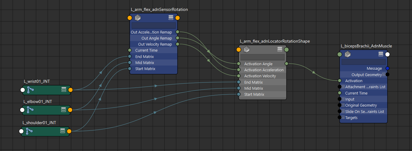
Figure 6: AdnSensorRotation and AdnLocatorRotation in the node graph .
Position in world space of the first transform node. This plug is used if: 1) it has input connections; 2) it does not have input connections and Start Matrix does not have input connections neither. Otherwise, Start Matrix is used instead.
Mid Position
Float3
{0.0, 0.0, 0.0}
✓
Position in world space of the second transform node. This plug is used if: 1) it has input connections; 2) it does not have input connections and Mid Matrix does not have input connections neither. Otherwise, Mid Matrix is used instead.
End Position
Float3
{0.0, 0.0, 0.0}
✓
Position in world space of the third transform node. This plug is used if: 1) it has input connections; 2) it does not have input connections and End Matrix does not have input connections neither. Otherwise, End Matrix is used instead.
Start Matrix
Matrix
Identity
✓
Matrix containing the position in world space of the first transform node. This plug is used if: 1) it has input connections and Start Position does not have input connections. Otherwise, Start Position is used instead.
Mid Matrix
Matrix
Identity
✓
Matrix containing the position in world space of the second transform node. This plug is used if: 1) it has input connections and Mid Position does not have input connections. Otherwise, Mid Position is used instead.
End Matrix
Matrix
Identity
✓
Matrix containing the position in world space of the third transform node. This plug is used if: 1) it has input connections and End Position does not have input connections. Otherwise, End Position is used instead.
Output
Name
Type
Default
Animatable
Description
Out Angle
Float
0.0
✗
Magnitude of the angle between the three transform nodes. It is the raw value calculated before the remapping.
Out Velocity
Float
0.0
✗
Magnitude of the angular velocity between the three transform nodes. It is the raw value calculated before the remapping.
Out Acceleration
Float
0.0
✗
Magnitude of the angular acceleration between the three transform nodes. It is the raw value calculated before the remapping.
Remapped Output
Name
Type
Default
Animatable
Description
Out Angle Remap
Float
0.0
✗
Output remapped angle. It is the result of remapping the Out Angle.
Out Velocity Remap
Float
0.0
✗
Output remapped velocity. It is the result of remapping the Out Velocity.
Out Acceleration Remap
Float
0.0
✗
Output remapped acceleration. It is the result of remapping the Out Acceleration.
Angle Remap Settings
Name
Type
Default
Animatable
Description
Selected Position
Float
0.0
✓
X-axis value of the ramp attribute.
Selected Value
Float
0.0
✓
Y-axis value of the ramp attribute.
Interpolation
Enumerator
Linear
✓
Interpolation method to be used between every two consecutive points in the ramp. There are four options: None, Linear, Smooth and Spline.
Input Min Angle
Float
3.14
✓
Lower limit of the range used to map the Out Angle value before evaluating it on the ramp attribute.
Input Max Angle
Float
0.0
✓
Upper limit of the range used to map the Out Angle value before evaluating it on the ramp attribute.
Output Min Angle
Float
0.0
✓
Lower limit of the range used to map the value returned by the ramp attribute and calculate the final remapped angle.
Output Max Angle
Float
1.0
✓
Upper limit of the range used to map the value returned by the ramp attribute and calculate the final remapped angle.
Velocity Remap Settings
Name
Type
Default
Animatable
Description
Selected Position
Float
0.0
✓
X-axis value of the ramp attribute.
Selected Value
Float
0.0
✓
Y-axis value of the ramp attribute.
Interpolation
Enumerator
Linear
✓
Interpolation method to be used between every two consecutive points in the ramp. There are four options: None, Linear, Smooth and Spline.
Input Min Velocity
Float
10.0
✓
Lower limit of the range used to map the Out Velocity value before evaluating it on the ramp attribute.
Input Max Velocity
Float
-10.0
✓
Upper limit of the range used to map the Out Velocity value before evaluating it on the ramp attribute.
Output Min Velocity
Float
0.0
✓
Lower limit of the range used to map the value returned by the ramp attribute and calculate the final remapped velocity.
Output Max Velocity
Float
1.0
✓
Upper limit of the range used to map the value returned by the ramp attribute and calculate the final remapped velocity.
Acceleration Remap Settings
Name
Type
Default
Animatable
Description
Selected Position
Float
0.0
✓
X-axis value of the ramp attribute.
Selected Value
Float
0.0
✓
Y-axis value of the ramp attribute.
Interpolation
Enumerator
Linear
✓
Interpolation method to be used between every two consecutive points in the ramp. There are four options: None, Linear, Smooth and Spline.
Input Min Acceleration
Float
10.0
✓
Lower limit of the range used to map the Out Acceleration value before evaluating it on the ramp attribute.
Input Max Acceleration
Float
-10.0
✓
Upper limit of the range used to map the Out Acceleration value before evaluating it on the ramp attribute.
Output Min Acceleration
Float
0.0
✓
Lower limit of the range used to map the value returned by the ramp attribute and calculate the final remapped acceleration.
Output Max Acceleration
Float
1.0
✓
Upper limit of the range used to map the value returned by the ramp attribute and calculate the final remapped acceleration.
Time Attributes
Name
Type
Default
Animatable
Description
Start Time
Time
Current frame
✗
Determines the frame at which the playback/simulation starts.
Current Time
Time
Current frame
✓
Current playback frame.
Scale Attributes
Name
Type
Default
Animatable
Description
Time Scale
Float
1.0
✓
Sets the scaling factor applied to the compute the velocity or acceleration. Has a range of [0.001, 10.0]. The upper limit is soft, higher values can be used.

 button in the AdonisFX shelf or press Position in the AdonisFX menu, under the Sensor submenu. If the shelf button is double-clicked or the option box in the menu is selected a window will be displayed where a custom name and initial attribute values can be set.
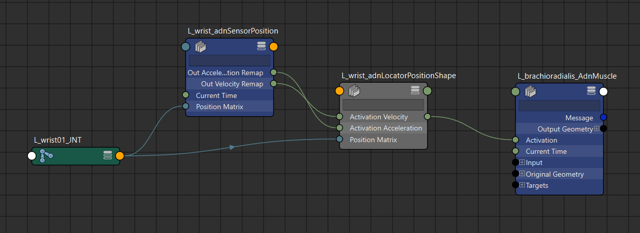
 button in the AdonisFX shelf or press Distance in the AdonisFX menu, under the Sensor submenu. If the shelf button is double-clicked or the option box in the menu is selected a window will be displayed where a custom name and initial attribute values can be set.
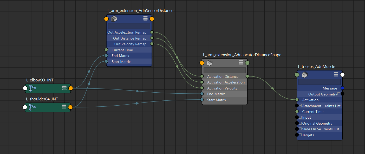
 button in the AdonisFX shelf or press Rotation in the AdonisFX menu, under the Sensor submenu. If the shelf button is double-clicked or the option box in the menu is selected a window will be displayed where a custom name and initial attribute values can be set.