AdnSkin
AdnSkin is a Maya deformer for fast, robust and easy-to-configure skin simulation for digital assets. Thanks to the combination of internal and external constraints, the deformer can produce dynamics that allow the skin mesh to realistically react to the deformations of internal tissues (e.g. muscles, fascia) over time.
The influence these constraints have on the simulated mesh can be freely modified by painting them via the AdonisFX Paint Tool or by uniformly regulating their influence via multipliers in the Attribute Editor. Besides the maps and multipliers there are many other parameters to regulate the skin's dynamics and behaviour to a wide array of options.
How To Use
The AdnSkin deformer is of great simplicity to set up and apply to a mesh within a Maya scene. The way this deformer works is by applying simulation on top of the skin mesh (simulated mesh) which will be directly coupled to its reference mesh (with deformation over time).
To create an AdnSkin deformer within a Maya scene, the following inputs must be provided:
- Reference Mesh (R): Mesh to drive the simulation skin (e.g. fascia or combined muscles).
- Skin Mesh (S): Mesh to apply the deformer onto.
The process to create an AdnSkin deformer is:
- Select the Reference Mesh, then the Skin Mesh.
- Press
 in the AdonisFX shelf or Skin in the AdonisFX menu, under the Create section. If the shelf button is double-clicked or the option box in the menu is selected a window will be displayed where a custom name and initial attribute values can be set.
 - A message box will notify you that AdnSkin has been created properly, meaning that it is ready to simulate with default settings. Check the next section to customise their configuration.
Attributes
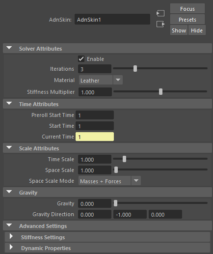
Solver Attributes
| Name | Type | Default | Animatable | Description |
|---|---|---|---|---|
| Enable | Boolean | True | ✓ | Flag to enable or disable the deformer computation. |
| Iterations | Integer | 3 | ✓ | Number of iterations that the solver will execute per simulation step. Greater values mean greater computational cost. Has a range of [1, 10]. Upper limit is soft, higher values can be used. |
| Material | Enumerator | Leather | ✓ | Solver stiffness presets per material. The materials are listed from lowest to highest stiffness. There are 7 different presets: Fat: 103, Muscle: 5e3, Rubber: 106, Tendon: 5e7, Leather: 106, Wood: 6e9, Concrete: 2.5e10. |
| Stiffness Multiplier | Float | 1.0 | ✓ | Multiplier factor to scale up or down the material stiffness. Has a range of [0.0, 2.0]. Upper limit is soft, higher values can be used. |
Time Attributes
| Name | Type | Default | Animatable | Description |
|---|---|---|---|---|
| Preroll Start Time | Time | Current frame | ✗ | Sets the frame at which the preroll begins. The preroll ends at Start Time. |
| Start Time | Time | Current frame | ✗ | Determines the frame at which the simulation starts. |
| Current Time | Time | Current frame | ✓ | Current playback frame. |
Scale Attributes
| Name | Type | Default | Animatable | Description |
|---|---|---|---|---|
| Time Scale | Float | 1.0 | ✓ | Sets the scaling factor applied to the simulation time step. Has a range of [0.0, 2.0]. Upper limit is soft, higher values can be used. |
| Space Scale | Float | 1.0 | ✓ | Sets the scaling factor applied to the masses and/or the forces (e.g. gravity). AdonisFX interprets the scene units in centimeters. If modeling your creature you apply a scaling factor for whatever reason (e.g. to avoid precision issues in Maya), you will have to adjust for this scaling factor using this attribute. If your character is supposed to be 170 units tall, but you preferred to model it to be 17 units tall, then you will need to set the space scale to a value of 10. This will ensure that your 17 units creature will simulate as if it was 170 units tall. Has a range of [0.0, 2.0]. Upper limit is soft, higher values can be used. |
| Space Scale Mode | Enumerator | Masses + Forces | ✓ | Determines if the spatial scaling affects the masses, the forces, or both. The available options are:
|
Gravity
| Name | Type | Default | Animatable | Description |
|---|---|---|---|---|
| Gravity | Float | 0.0 | ✓ | Sets the magnitude of the gravity acceleration in m/s2. The value is internally converted to cm/s2. Has a range of [0.0, 100.0]. Upper limit is soft, higher values can be used. |
| Gravity Direction | Float3 | {0.0, -1.0, 0.0} | ✓ | Sets the direction of the gravity acceleration. Vectors introduced do not need to be normalised, but they will get normalised internally. |
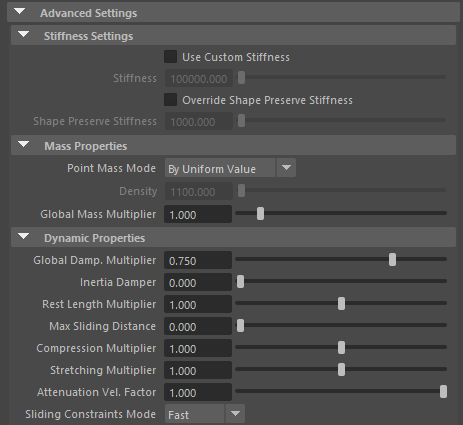
Advanced Settings
Stiffness Settings
| Name | Type | Default | Animatable | Description |
|---|---|---|---|---|
| Use Custom Stiffness | Boolean | False | ✓ | Toggles the use of a custom stiffness value. If custom stiffness is used, Material and Stiffness Multiplier will be disabled and Stiffness will be used instead. |
| Stiffness | Float | 105 | ✓ | Sets the custom stiffness value. Its value must be greater than 0.0. |
| Override Shape Preserve Stiffness | Boolean | False | ✓ | Override the shape preservation stiffness with a custom value. If disabled it will use either the material stiffness or the custom stiffness value. |
| Shape Preserve Stiffness | Float | 103 | ✓ | Sets the stiffness shape preservation override value. Its value must be greater than 0.0. |
Mass Properties
| Name | Type | Default | Animatable | Description |
|---|---|---|---|---|
| Point Mass Mode | Enumerator | By Uniform Value | ✓ | Defines how masses should be used in the solver.
|
| Density | Float | 1100.0 | ✓ | Sets the density value in kg/m3 to be able to estime mass values with By Density mode. The value is internally converted to g/cm3. Has a range of [0.001, 106]. Lower and upper limits are soft, lower and higher values can be used. |
| Global Mass Multiplier | Float | 1.0 | ✓ | Sets the scaling factor applied to the mass of every point. Has a range of [0.001, 10.0]. Lower and upper limits are soft, lower and higher values can be used. |
Dynamic Properties
| Name | Type | Default | Animatable | Description |
|---|---|---|---|---|
| Global Damping Multiplier | Float | 0.75 | ✓ | Sets the scaling factor applied to the global damping of every point. Has a range of [0.0, 1.0]. Upper limit is soft, higher values can be used. |
| Inertia Damper | Float | 0.0 | ✓ | Sets the linear damping applied to the dynamics of every point. Has a range of [0.0, 1.0]. Upper limit is soft, higher values can be used. |
| Rest Length Multiplier | Float | 1.0 | ✓ | Sets the scaling factor applied to the edge lengths at rest. Has a range of [0.0, 2.0]. Upper limit is soft, higher values can be used. |
| Max Sliding Distance | Float | 0.0 | ✗ | Determines the size of the sliding area. It corresponds to the maximum distance to the closest point on the reference mesh computed on initialisation. The higher this value is, the higher quality and the lower performance. If the value provided is considered too high for a given reference mesh, a warning will be displayed to the user. Has a range of [0.0, 10.0]. Upper limit is soft, higher values can be used. |
| Compression Multiplier | Float | 1.0 | ✓ | Sets the scaling factor applied to the compression resistance of every point. Has a range of [0.0, 2.0]. Upper limit is soft, higher values can be used. |
| Stretching Multiplier | Float | 1.0 | ✓ | Sets the scaling factor applied to the stretching resistance of every point. Has a range of [0.0, 2.0]. Upper limit is soft, higher values can be used. |
| Attenuation Velocity Factor | Float | 1.0 | ✓ | Sets the weight of the attenuation applied to the velocities of the simulated vertices driven by the Attenuation Matrix. Has a range of [0.0, 1.0]. Upper limit is soft, higher values can be used. |
| Sliding Constraints Mode | Enumerator | Fast | ✓ | Defines the mode of execution for the sliding constraints.
|
Debug Attributes
| Name | Type | Default | Animatable | Description |
|---|---|---|---|---|
| Debug | Boolean | False | ✓ | Enable or Disable the debug functionalities in the viewport for the AdnSkin deformer. |
| Feature | Enumerator | Hard Constraints | ✓ | A list of debuggable features for this deformer.
|
| Width Scale | Float | 3.0 | ✓ | Modifies the width of all lines. |
| Color | Color Picker | ✓ | Selects the line colour from a colour wheel. Its saturation can be modified using the slider. |
Deformer Attributes
| Name | Type | Default | Animatable | Description |
|---|---|---|---|---|
| Envelope | Float | 1.0 | ✓ | Specifies the deformation scale factor. Has a range of [0.0, 1.0]. Upper and lower limits are soft, values can be set in a range of [-2.0, 2.0] |
Connectable Attributes
| Name | Type | Default | Animatable | Description |
|---|---|---|---|---|
| Attenuation Matrix | Matrix | Identity | ✓ | Transformation matrix to drive the attenuation. |
| Reference Matrix | Mesh | ✓ | Mesh taken as reference to evaluate external constraints. |
Attribute Editor Template
Paintable Weights
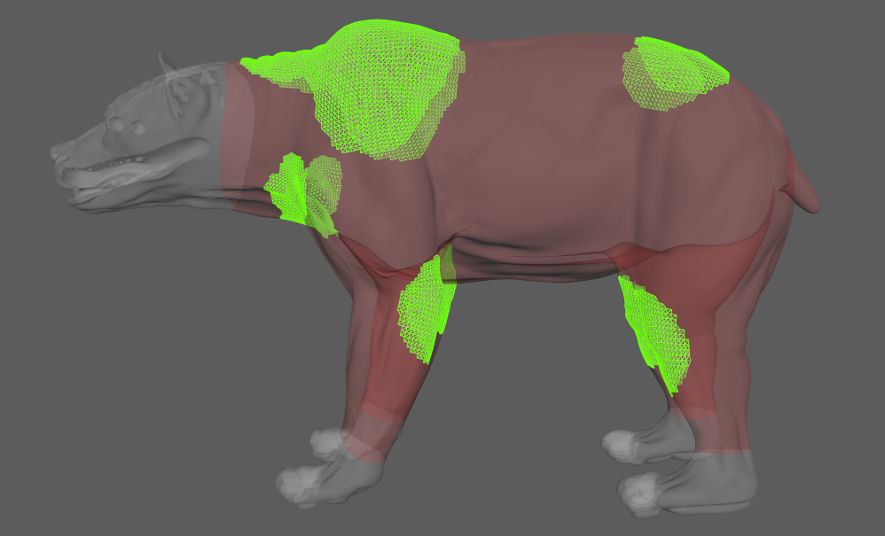
In order to provide more artistic control, some key parameters of the AdnSkin solver are exposed as paintable attributes in the deformer. The AdonisFX Paint Tool must be used to paint those parameters to ensure that the values satisfy the solver requirements.
| Name | Default | Description |
|---|---|---|
| Compression Resistance | 1.0 | Force to correct the edge lengths if the current length is smaller than the rest length. A higher value represents higher correction.
|
| Global Damping | 1.0 | Set global damping per vertex in the simulated mesh. The greater the value per vertex is the more damping of velocities. |
| Hard Constraints | 1.0 | Weight to modulate the correction applied to the vertices to keep them at a constant transformation, local to the closest point on the reference mesh at initialisation. Hard Constraint maps will force the geometry points to keep the original position. A low value of Hard Constraints may be desired to allow the skin to create wrinkles and sliding effect.
|
| Masses | 1.0 | Set individual mass values per vertex in the simulated mesh. |
| Shape Preservation | 0.0 | Amount of correction to apply to the current vertex to maintain the initial state of the shape formed with the surrounding vertices. |
| Slide Constraints | 0.0 | Weight to modulate the correction applied to the vertices to keep them at a constant distance to the reference mesh sliding along the reference surface.
|
| Sliding Distance Multiplier | 1.0 | Determines the size of the sliding area per vertex. It corresponds to the maximum distance to the closest point on the reference mesh computed on initialisation. Greater values will allow for larger sliding areas but will also increase the computational cost.
|
| Soft Constraints | 0.0 | Weight to modulate the correction applied to the vertices to keep them at a constant distance to the closest point on the reference mesh at initialisation. Painting these constraint weights would allow the deformer to create a wrinkle effect when combined with hard and slide weights.
|
| Stretching Resistance | 1.0 | Force to correct the edge lengths if the current length is greater than the rest length. A higher value represents higher correction.
|
a) Compression Resistance, b) Global Damping, c) Hard Constraints, d) Mass,
e) Shape Preservation, f) Slide Constraints, g) Sliding Distance Multiplier, h) Soft Constraints, and i) Stretching Resistance.
Hard, Soft and Slide values are normalised for each vertex. Make sure to paint the values that you want to give priority to at the end in order to avoid the internal normalisation override them in further strokes.
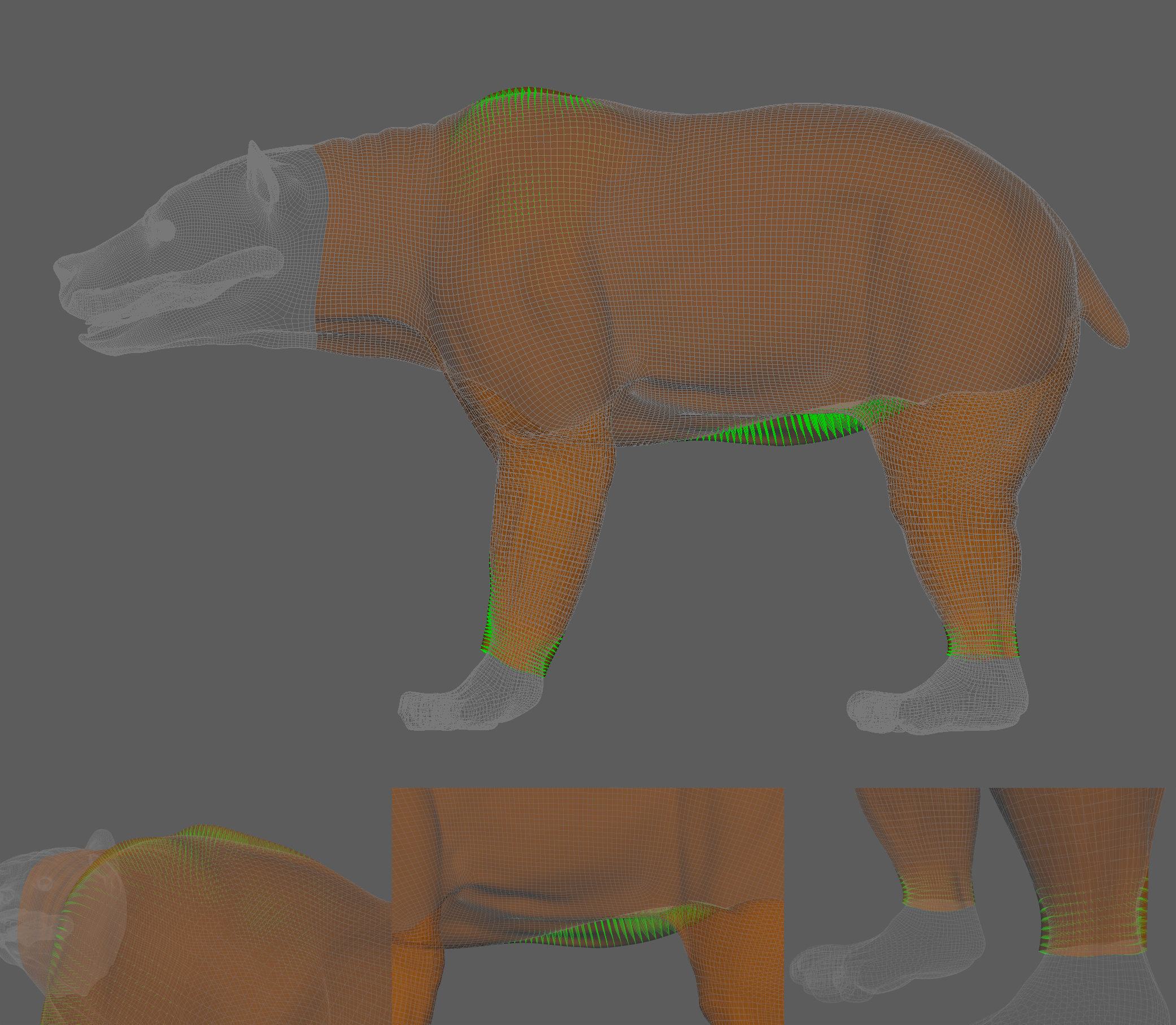
Debugger
In order to better visualise deformer constraints and attributes in the Maya viewport there is the option to enable the debugger, found in the dropdown menu labeled Debug in the Attribute Editor.
To enable the debugger the Debug checkbox must be marked. To select the specific feature you would like to visualise, choose it from the list provided in Features. The features that can be visualised with the debugger in the AdnSkin deformer are:
- Hard Constraints: For each vertex, a line will be drawn from the simulated mesh vertex to the corresponding point on the reference mesh if its Hard Constraints weight is greater than 0.0.
- Shape Preservation: For each vertex with a shape preservation weight greater than 0.0, a line will be drawn from each adjacent vertex to the opposite adjacent vertex.
- Slide Constraints: For each vertex, a line will be drawn from the simulated mesh vertex to the corresponding point on the reference mesh if its Slide Constraints weight is greater than 0.0.s
- Sliding Surface On Target: For each vertex, lines will outline the target triangles within the reach of its Max Sliding Distance.
- Soft Constraints: For each vertex, a line will be drawn from the simulated mesh vertex to the corresponding point on the reference mesh if its Soft Constraints weight is greater than 0.0.