< Inspecting and Authoring Properties Converting Between Layer Formats >
¶Referencing Layers
This tutorial is focused on creating a new stage that references the stage created in the previous tutorials, using the operators from the Shift_USD catalog. The example will reuse the HelloWorld.usda file generated during the last tutorial Inspecting and Authoring Properties.
The USD file HelloWorld.usda can be found in the following path in the Shift installation folder: <path_to_the_shift_installation_folder>/shift/examples/USD/tutorials/tutorial_02_authoring_properties/result/.
¶Tutorial
- Open Shift application. A new window instance of Shift should appear like the following one:
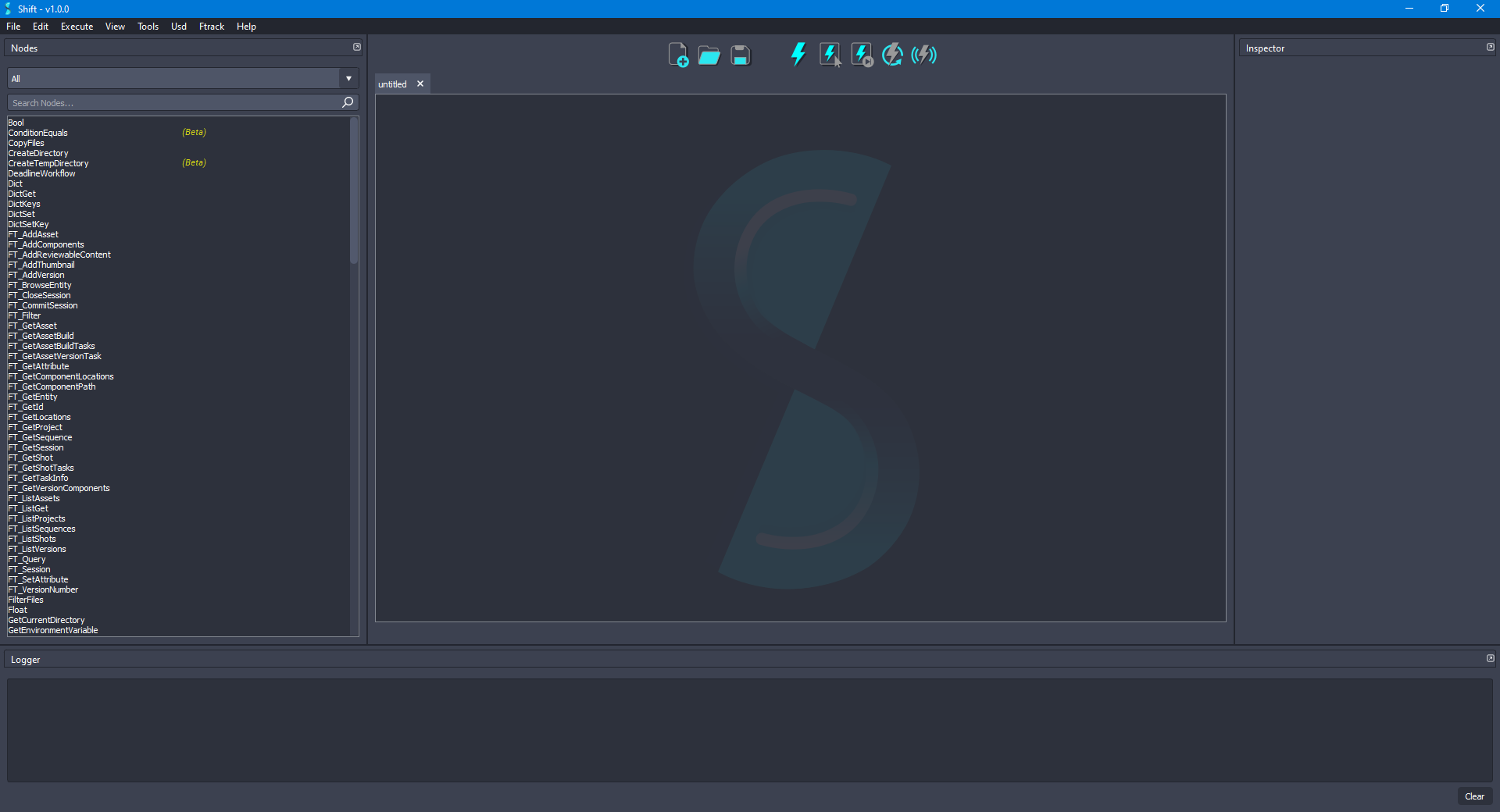
Before creating the USD workflow, ensure that the USD nodes appear in the Node List widget. The catalogs combobox should show
sUSDandsUSDTypesif USD is correctly loaded in Shift. If this is not the case, please check again the Shift_USD installation page.
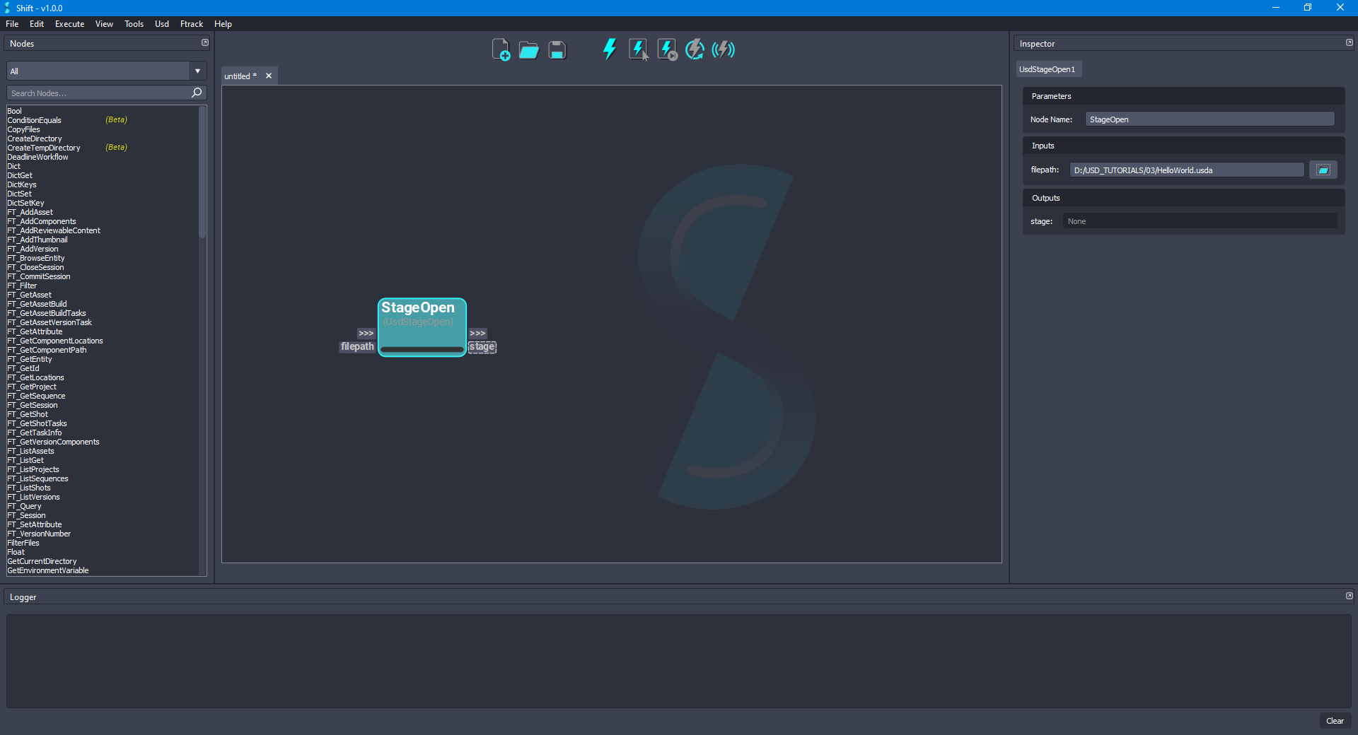
- Add a new UsdStageOpen node to the board and rename it to StageOpen. Using the Inspector widget, set as the value for the filepath plug a filepath pointing to the
HelloWorld.usdafile downloaded for the example. The board should look like the following:
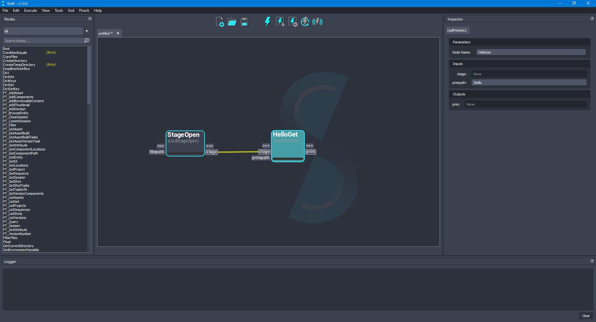
- Add a new UsdPrimGet node to the board and rename it to HelloGet. Connect the stage output plug from the StageOpen node to the stage input plug of the new node. Set
/helloas the value to the primpath input plug. The board should look like the following:
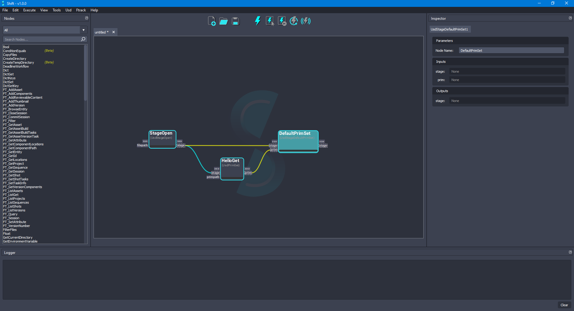
- Add a new UsdStageDefaultPrimSet node to the board and rename it to DefaultPrimSet. Connect the stage output plug from the StageOpen node to the stage input plug of the new node, also, connect the prim output plug from the HelloGet node to the prim input plug of the new node. The board should look like the following:
- For adding a translation to the
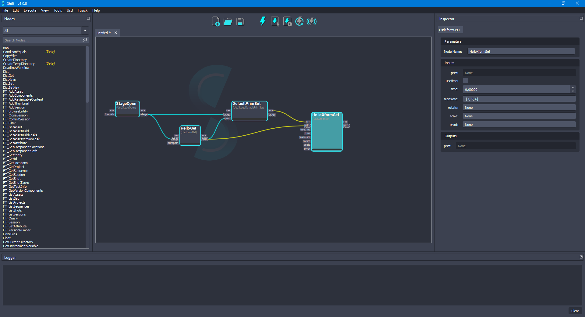
Helloprim, add a new UsdXformSet node to the board and rename it to HelloXformSet. Connect the prim output plug from the HelloGet node to the prim input plug of the new node and connect the out-trigger from the DefaultPrimSet node to the in-trigger of the new node. Set[4, 5, 6]as the value for the translate input plug, leave the useTime input plug value set asFalse, the time input plug value set as0, and the rotate, scale and pivot input plugs values set asNone. The board should look like the following:
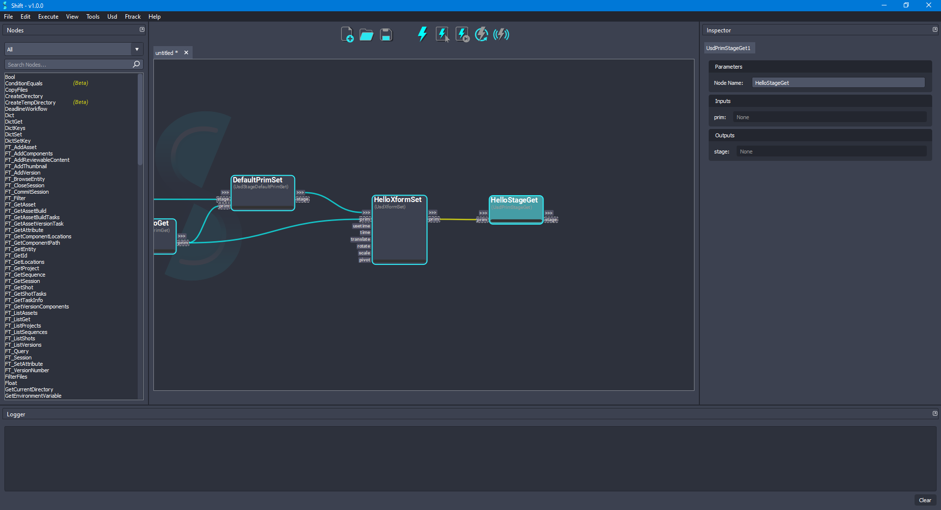
- Add a new UsdPrimStageGet node to the board and rename it to HelloStageGet. Connect the prim output plug from the HelloXformSet node to the prim input plug of the new node. The board should look like the following:
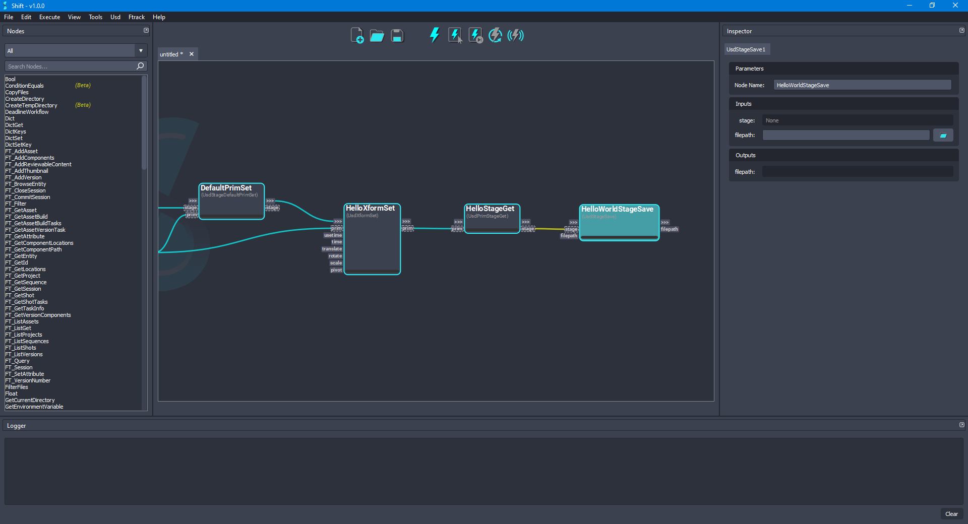
- Add a new UsdStageSave node to the board and rename it to HelloWorldStageSave. Connect the stage output plug from the HelloStageGet node to the stage input plug of the new node. Leave the filepath input plug empty to override the original file. The board should look like the following:
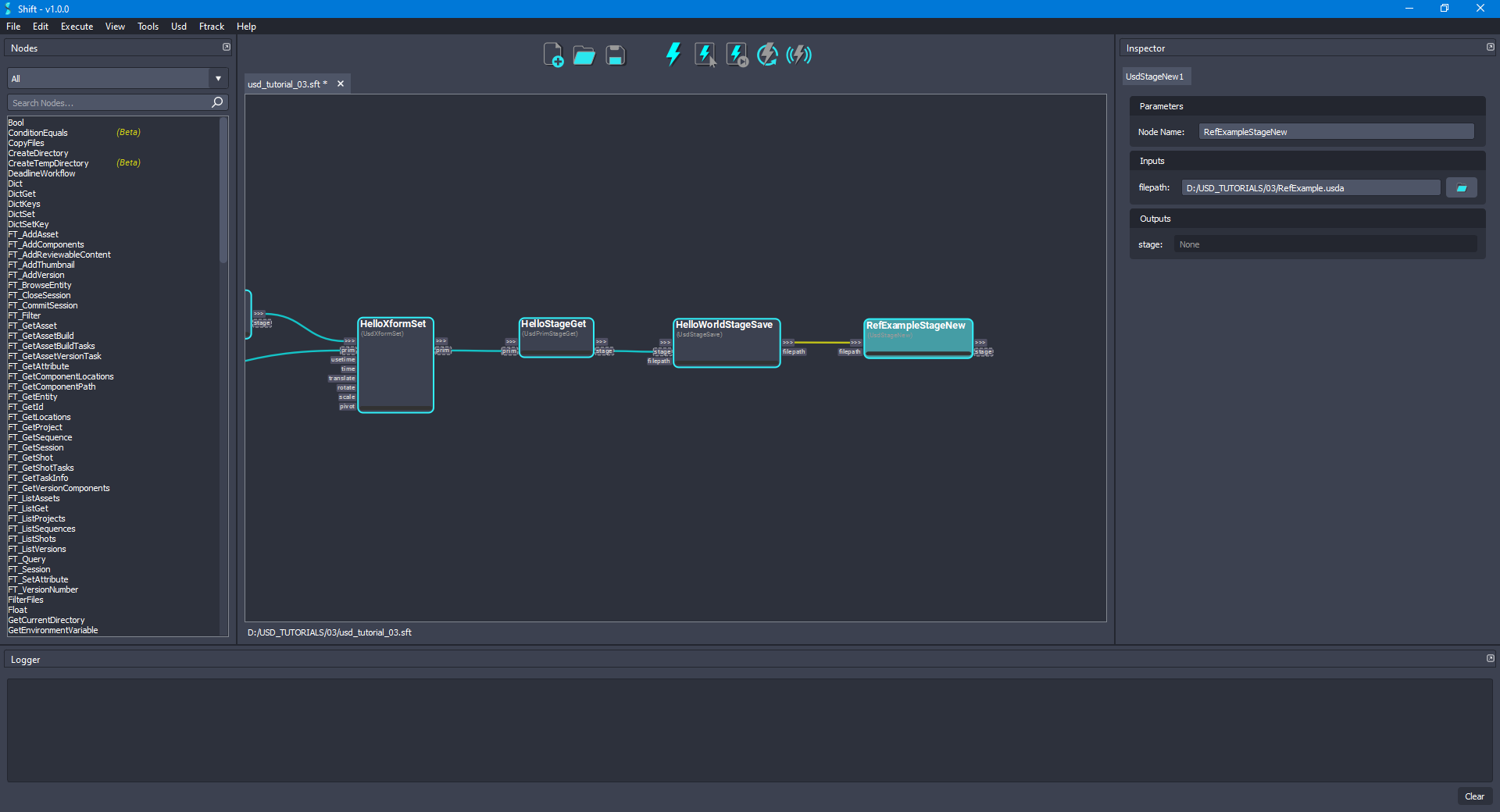
- Add a new UsdStageNew node to the board and rename it to RefExampleStageNew. Connect the out-trigger output plug from the HelloWorldStageSave node to the in-trigger input plug of the new node. Set as the value for the filepath input plug a filepath pointing to a file named
RefExample.usda. That file will be used for adding references to the previous modified stage. The board should look like the following:
- For overriding a prim in a stage, add a new UsdPrimOverride node to the board and rename it to RefSphereOverride. Connect the stage output plug from the RefExampleStageNew node to the stage input plug of the new node. Set
/refSphereas the value for the primpath input plug. The board should look like the following:
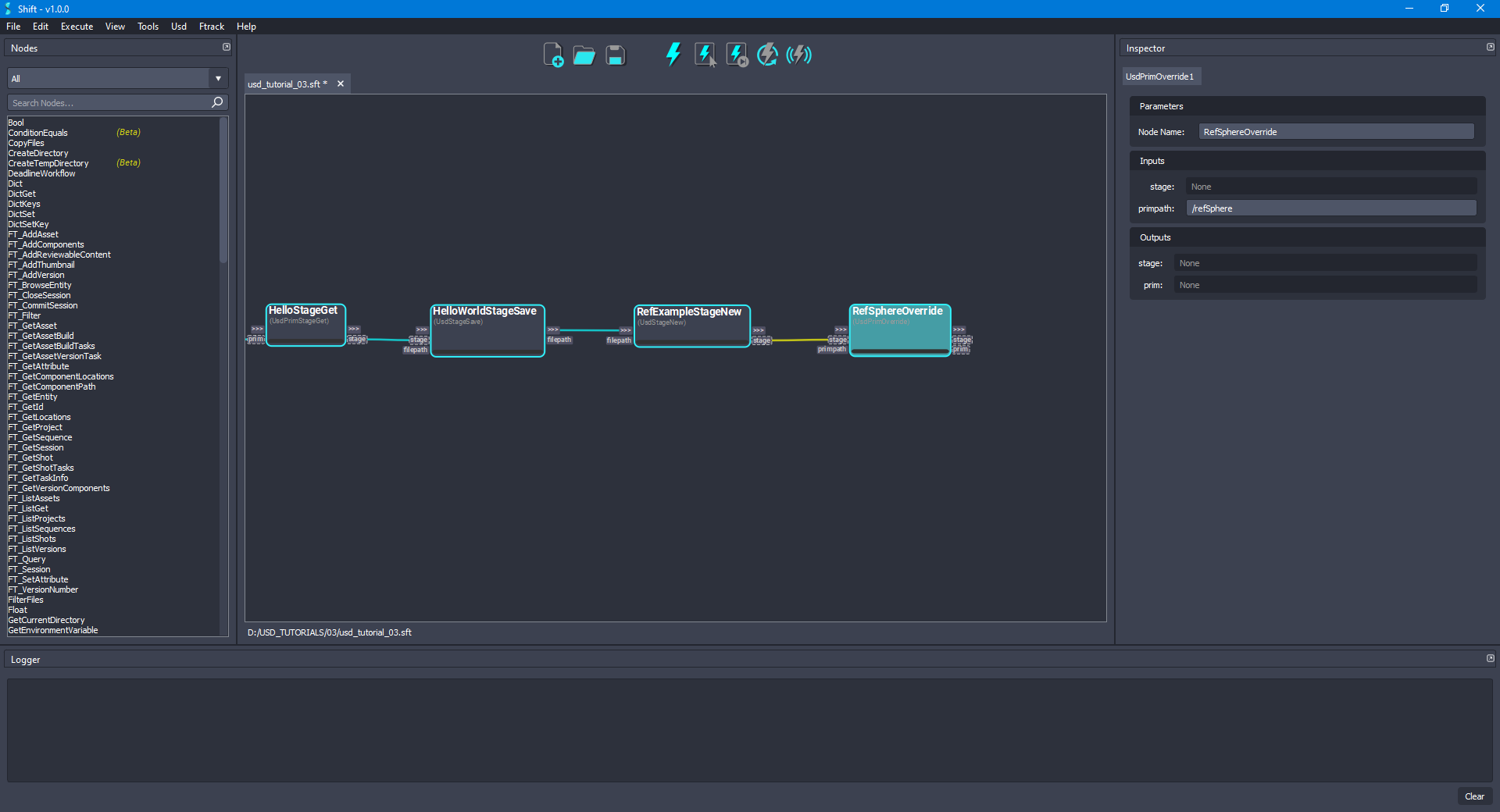
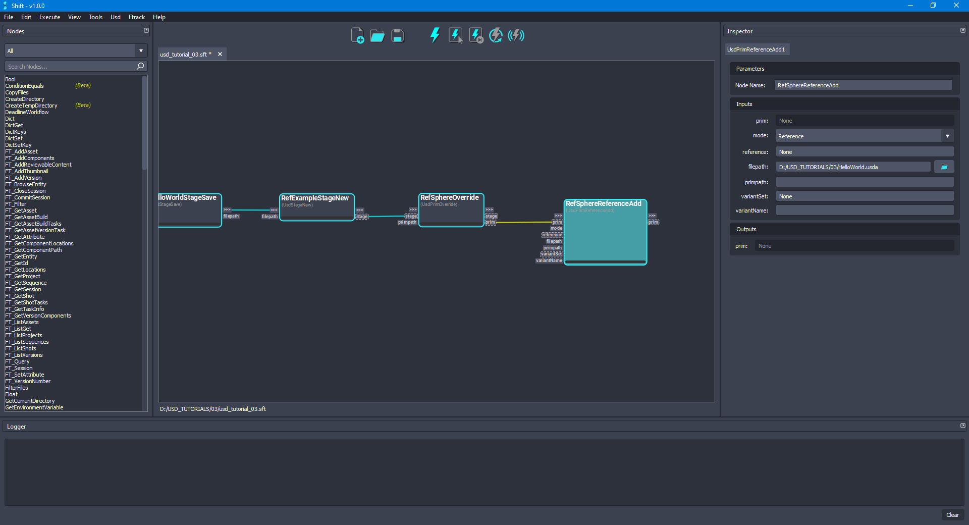
- Add a new UsdPrimReferenceAdd node to the board and rename it to RefSphereReferenceAdd. Connect the prim output plug from the RefSphereOverride node to the prim input plug of the new node. Set
Referenceas the value for the mode input plug andNoneas the value for the reference input plug. For the filepath input plug, set as value the path to the updatedHelloWorld.usdafile used at the beginning of the tutorial,D:/USD_TUTORIALS/03/HelloWorld.usda. Leave the value empty for the primpath input plug,Noneas the value for the variantSet input plug and empty value for the variantName input plug. The board should look like the following:
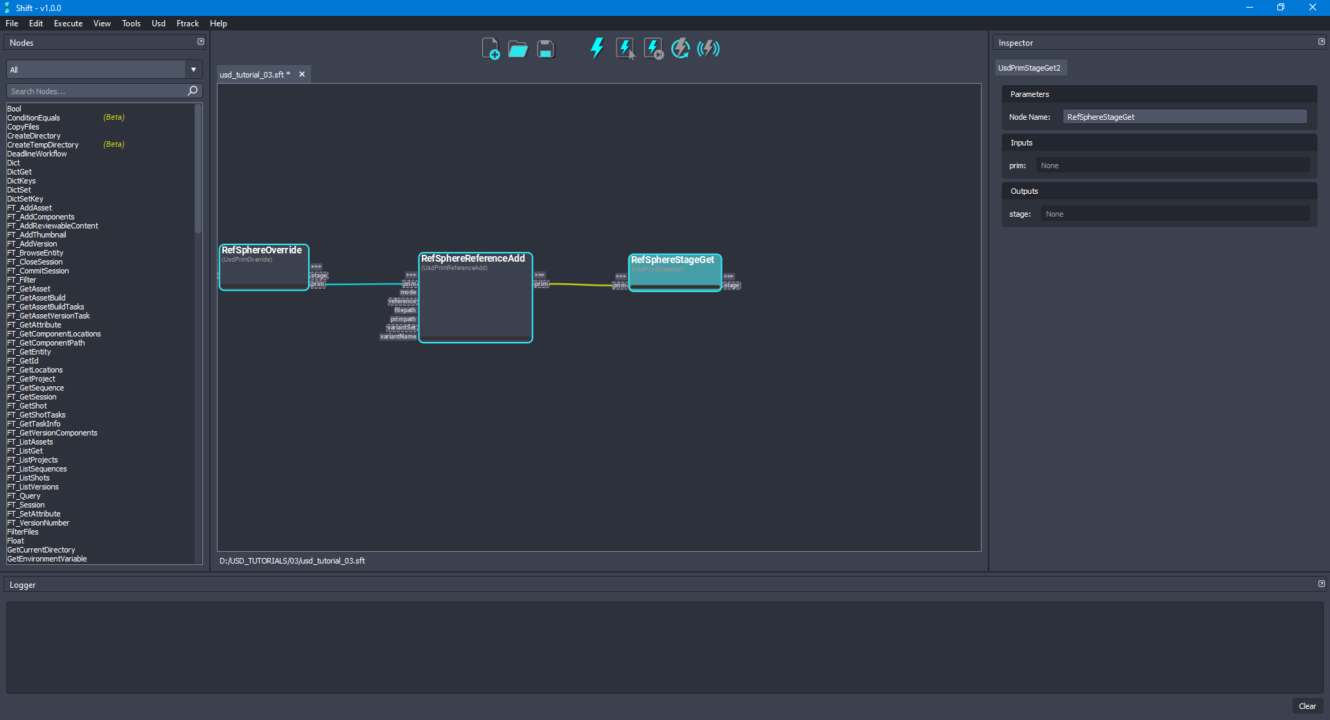
- Add another UsdPrimStageGet node to the board and rename it to RefSphereStageGet. Connect the prim output plug from the RefSphereReferenceAdd node to the prim input plug of the new node. The board should look like the following:
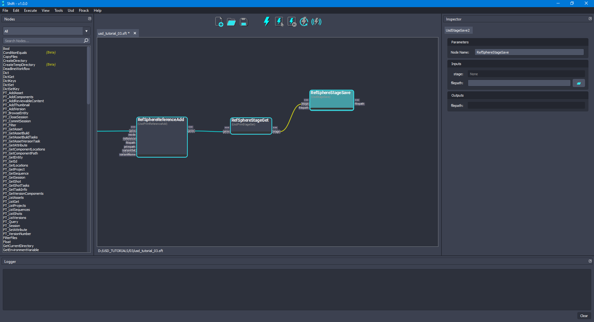
- Add another UsdStageSave node to the board and rename it to RefSphereStageSave. Connect the stage output plug from the RefSphereStageGet node to the stage input plug of the new node. Leave the filepath input plug empty to override the original file. The board should look like the following:
- In order to reset the transform of the
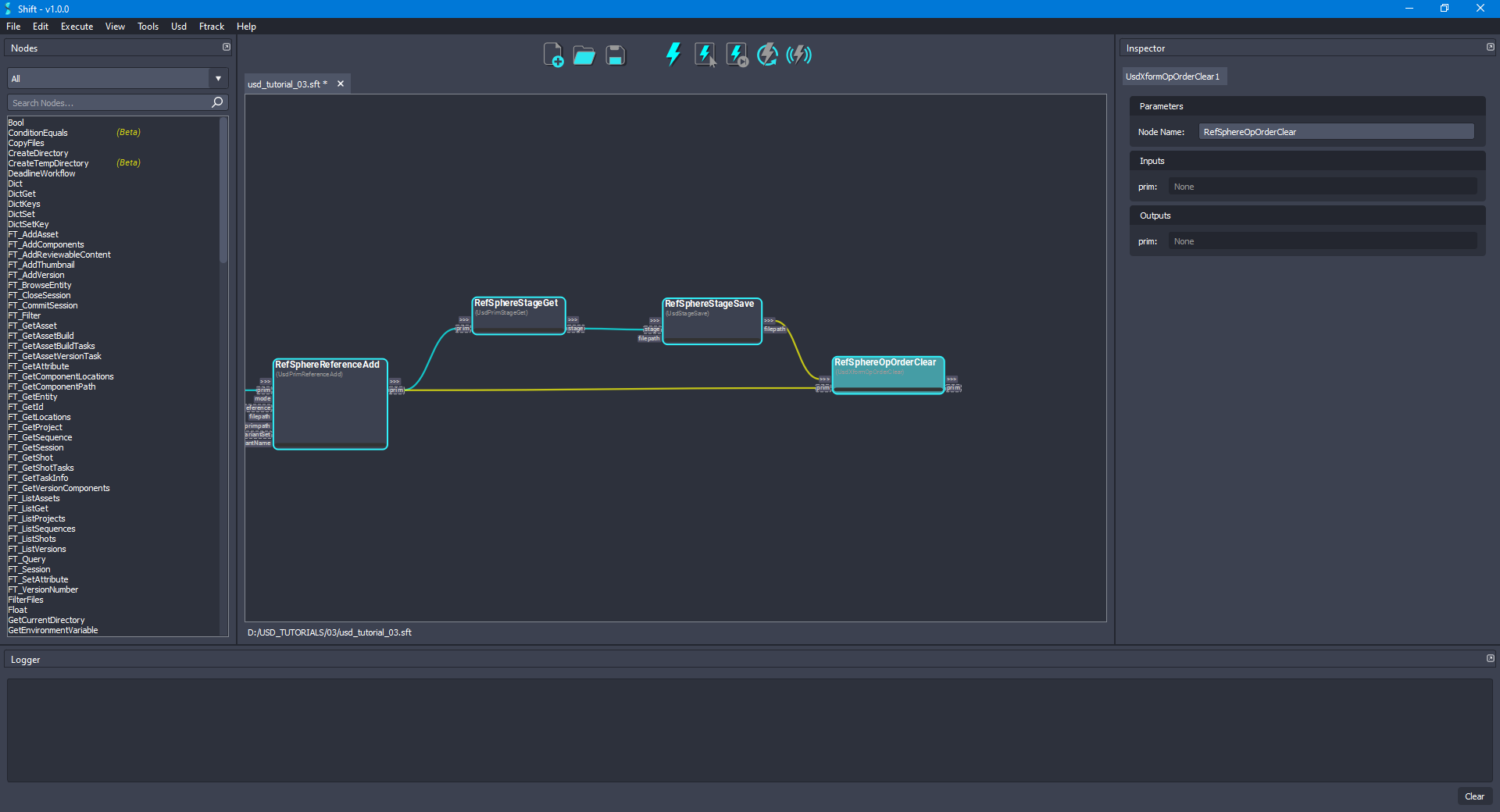
/refSphereprim, add a new UsdXformOpOrderClear node to the board and rename it to RefSphereOpOrderClear. Connect the prim output plug from the RefSphereReferenceAdd node to the prim input plug of the new node, also, connect the out-trigger output plug from the RefSphereStageSave node to the in-trigger plug of the new node. The board should look like the following:
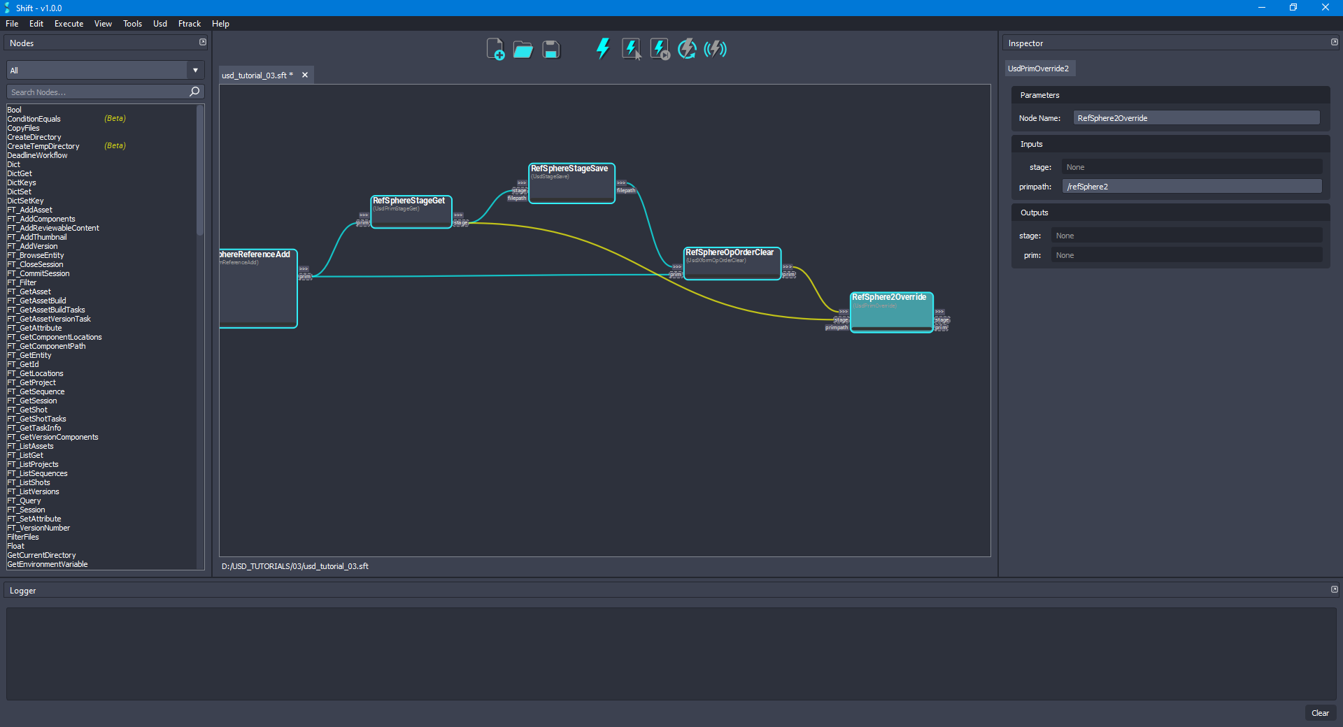
- Add a new UsdPrimOverride node to the board and rename it to RefSphere2Override. Connect the stage output plug from the RefSphereStageGet node to the stage input plug of the new node, also, connect the out-trigger output plug from the RefSphereOpOrderClear node to the in-trigger input plug of the new node. Set
/refSphere2as the value for the primpath input plug. The board should look like the following:
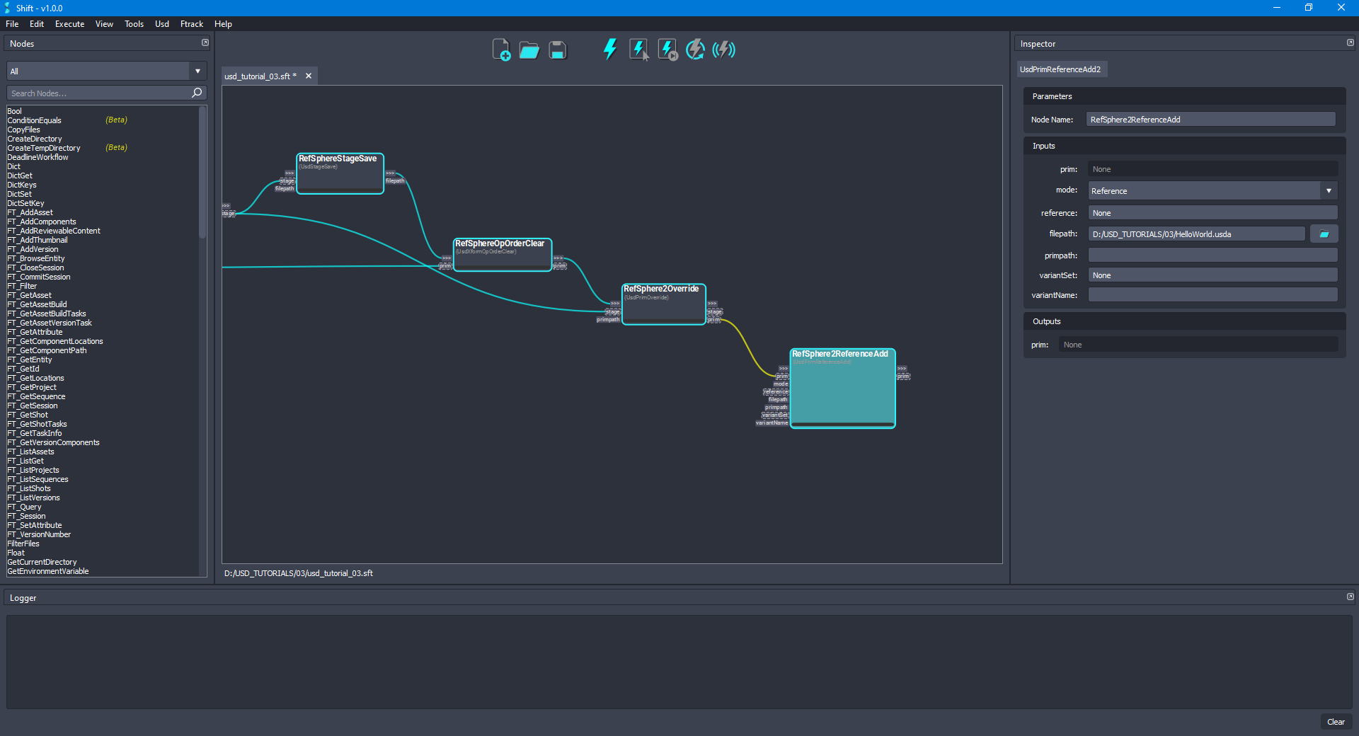
- Add another UsdPrimReferenceAdd node to the board and rename it to RefSphere2ReferenceAdd. Connect the prim output plug from the RefSphere2Override node to the prim input plug of the new node. As done in the previous step 10, set
Referenceas the value for the mode input plug andNoneas the value for the reference input plug. For the filepath input plug, set as value the path to the updatedHelloWorld.usdafile used at the beginning of the tutorial,D:/USD_TUTORIALS/03/HelloWorld.usda. Leave the value empty for the primpath input plug,Noneas the value for the variantSet input plug and empty value for the variantName input plug. The board should look like the following:
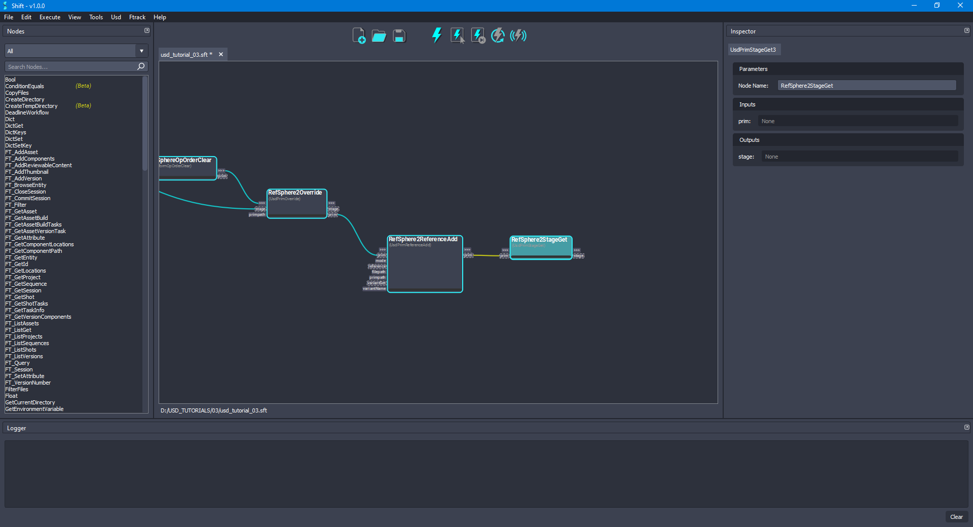
- Add a new UsdPrimStageGet node to the board and rename it to RefSphere2StageGet. Connect the prim output plug from the RefSphere2ReferenceAdd node to the prim input plug of the new node. The board should look like the following:
- Add another UsdStageSave node to the board and rename it to RefSphere2StageSave. Connect the stage output plug from the RefSphere2StageGet node to the stage input plug of the new node. Leave empty the value for the filepath input plug, doing this, the original file will be overriden. The board should look like the following:
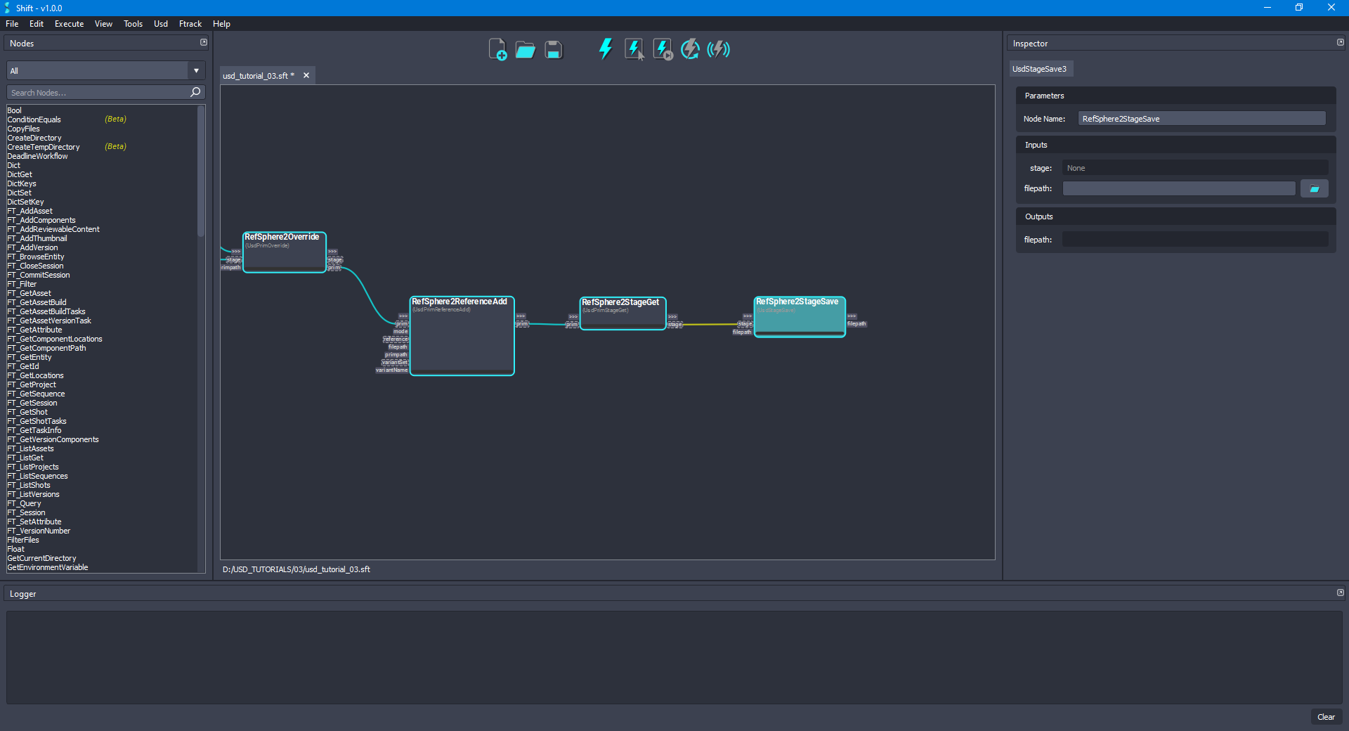
- Add a new UsdPrimGet node to the board and rename it to WorldGet. Connect the stage output plug from the RefSphere2StageGet node to the stage input plug of the new node. Set
/refSphere2/worldas the value of the primpath input plug of the new node. Also, connect the out-trigger output plug from the RefSphere2StageSave node to the in-trigger input plug of the new node. The board should look like the following:
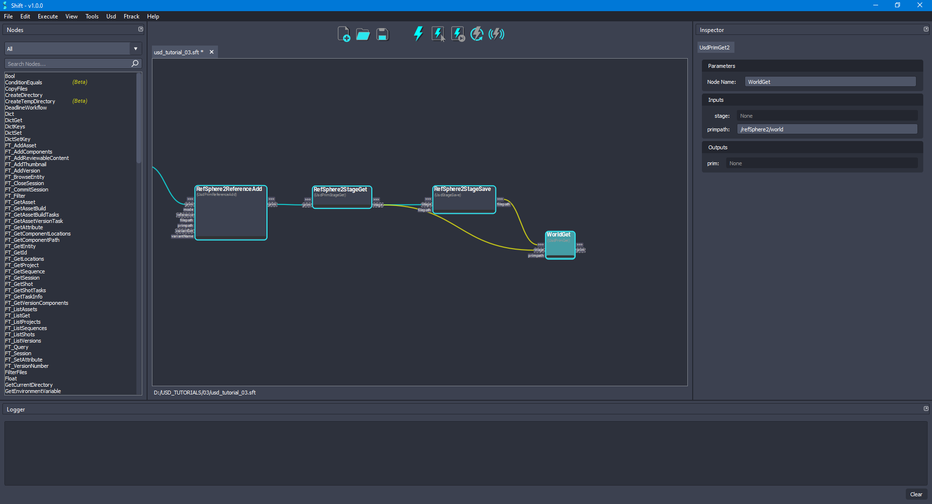
- Add a new UsdPrimDisplayColorSet node to the board and rename it to WorldDisplayColorSet. Connect the prim output plug from the WorldGet node to the prim input plug of the new node. Set
[1, 0, 0]as the value for the color input plug,[]as the value for the indices input plug andconstantas the value for the interpolation input plug of the new node. The board should look like the following:
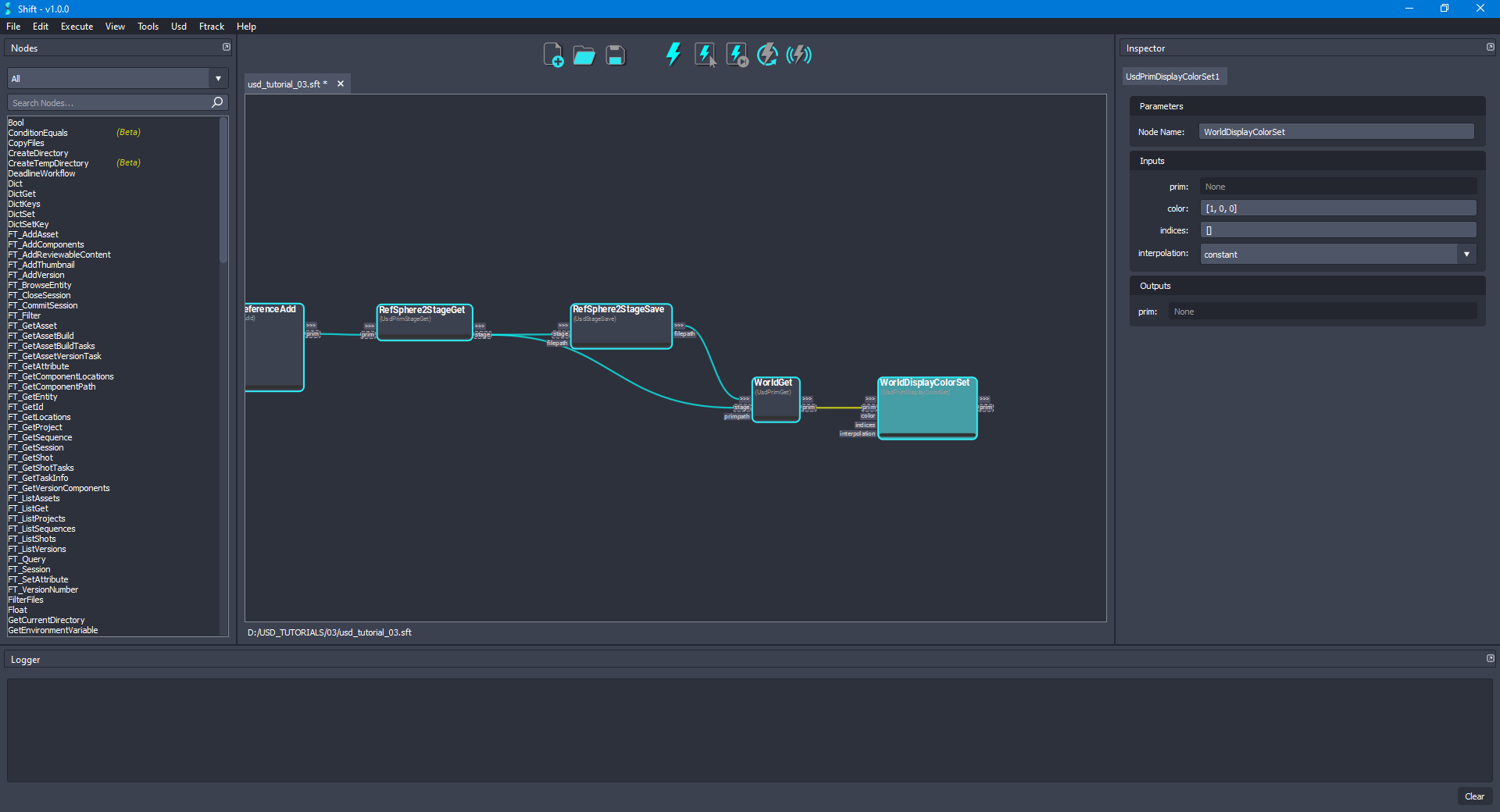
- Add another UsdPrimStageGet node to the board and rename it to WorldStageGet. Connect the prim output plug from the WorldDisplayColorSet node to the prim input plug of the new node. The board should look like the following:
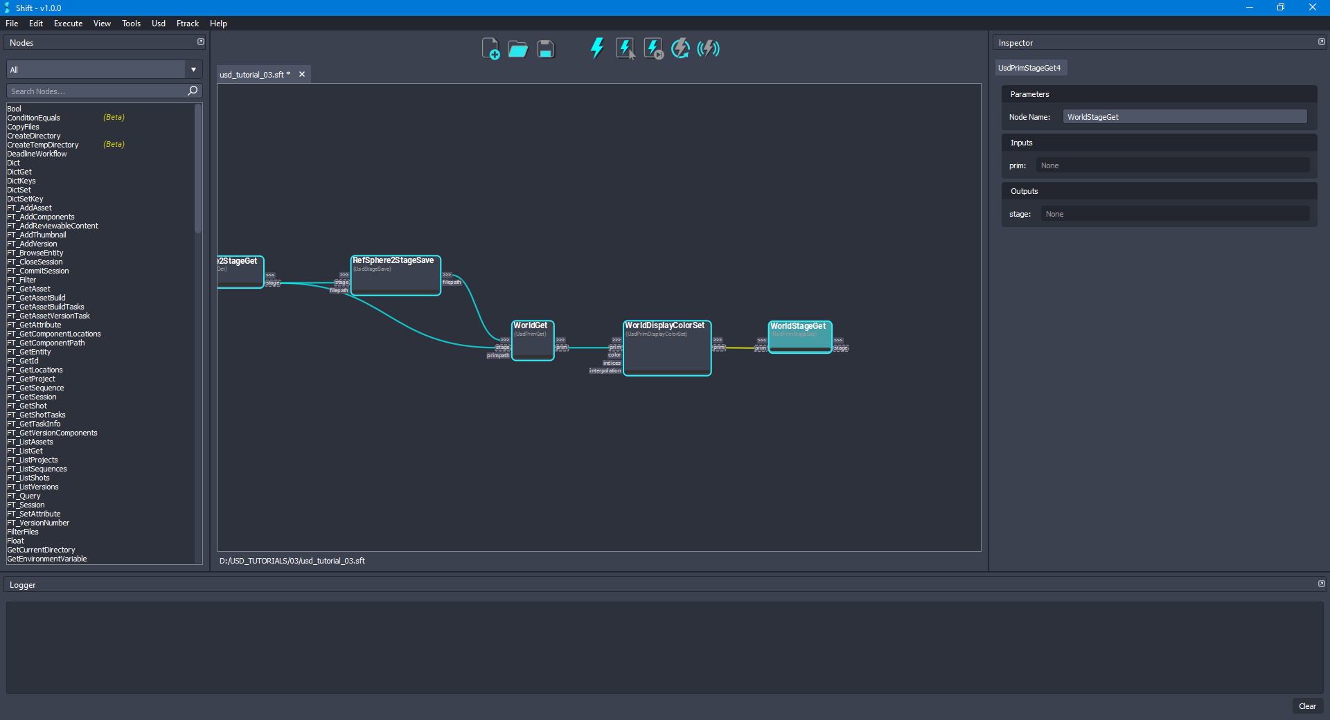
- Add another UsdStageSave node to the board and rename it to WorldStageSave. Connect the stage output plug from the WorldStageGet node to the stage input plug of the new node. Leave empty the value for the filepath input plug, doing this, the original file will be overridden. The board should look like the following:
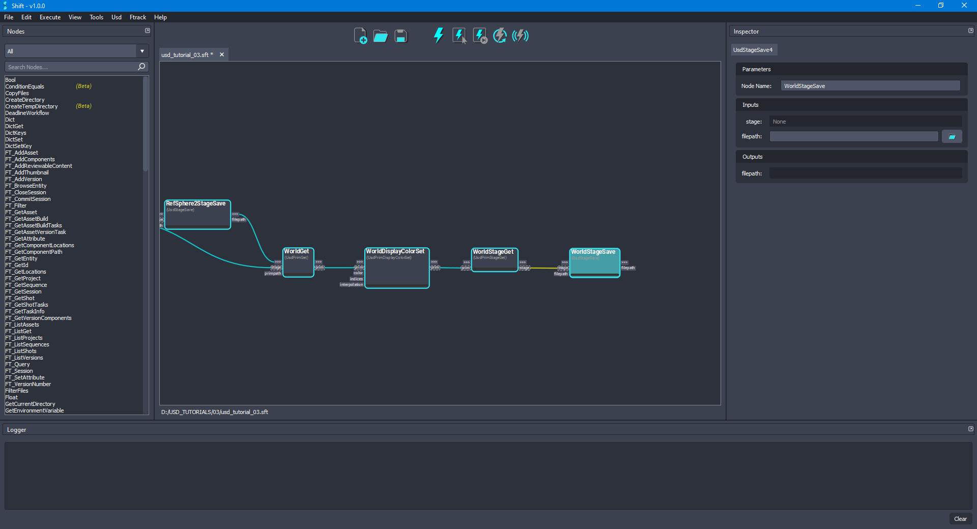
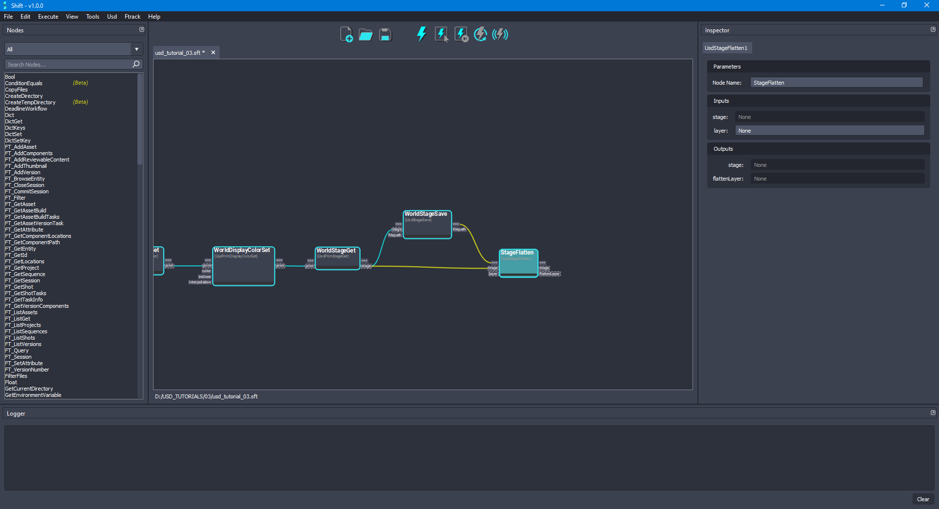
- To flatten the resulting stage, add a new UsdStageFlatten node to the board and rename it to StageFlatten. Connect the stage output plug from the WorldStageGet node to the stage input plug of the new node. Leave the layer input plug with the default value to
None. Finally, connect the out-trigger output plug from the WorldStageSave node to the in-trigger input plug of the new node. The board should look like the following:
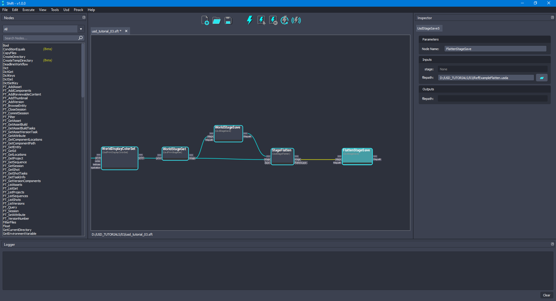
- For saving the stage after flattening it, add another UsdStageSave node to the board and rename it to FlattenStageSave. Connect the stage output plug from the StageFlatten node to the stage input plug of the new node. Now, set the value for the filepath input plug to point to a new
.usdafile to avoid overwriting the final result, for example,D:/USD_TUTORIALS/03/RefExampleFlatten.usda. The board should look like the following:
- Execute the entire workflow. Open the
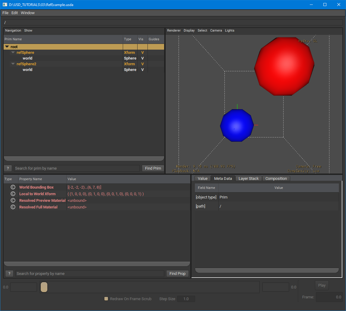
RefExample.usdafile, it will contain the references and overrides updated. Also, preview theRefExampleFlatten.usdafor checking how flattening the stage works.
¶Visualising the Stage
Shift is shipped with native plugins to visualise and inspect the stage. They can be accessed from the USD top menu:
-
USD Outliner: Shows the user the stage hierarchy sourced from specific Usd nodes in the active board workflow.
-
USD Viewer: Shows the stage in the USD viewer sourced from specific USD nodes in the active board workflow.
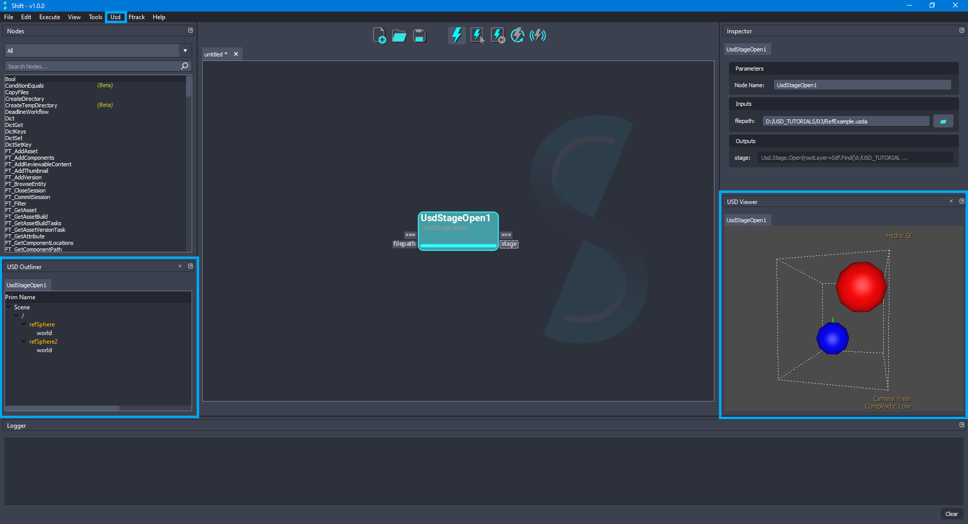
The USD viewer tool shipped with USD is used to visualise and inspect the stage viewport:
¶Workflow Resources
The workflow corresponding to this tutorial can be found in the following path in the Shift installation folder: <path_to_the_shift_installation_folder>/shift/examples/USD/tutorials/tutorial_03_referencing_layers/tutorial_03.sft
< Inspecting and Authoring Properties Converting Between Layer Formats >


