< Traversing a Stage Main USD Tutorials Page >
¶Authoring Variants
This tutorial focuses on creating and authoring a variant set using the HelloWorld layer from the Inspecting and Authoring Properties tutorial, using the operators from Shift_USD catalog.
The USD file HelloWorld.usda can be found in the following path in the Shift installation folder: <path_to_the_shift_installation_folder>/shift/examples/USD/tutorials/tutorial_02_authoring_properties/result/.
¶Tutorial
- Open Shift application. A new window instance of Shift should appear like the following one:
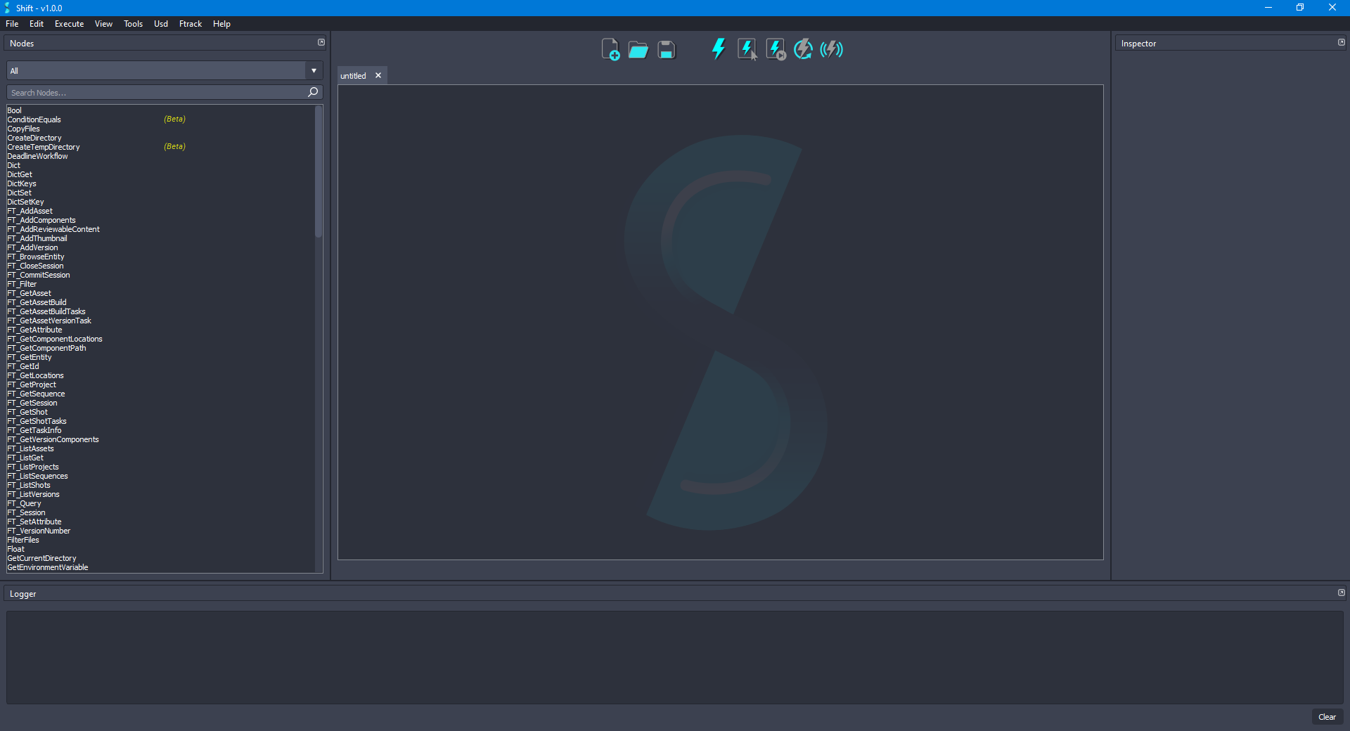
Before creating the USD workflow, ensure that the USD nodes appear in the Node List widget. The catalogs combobox should show
sUSDandsUSDTypesif USD is correctly loaded in Shift. If this is not the case, please check again the Shift_USD installation page.
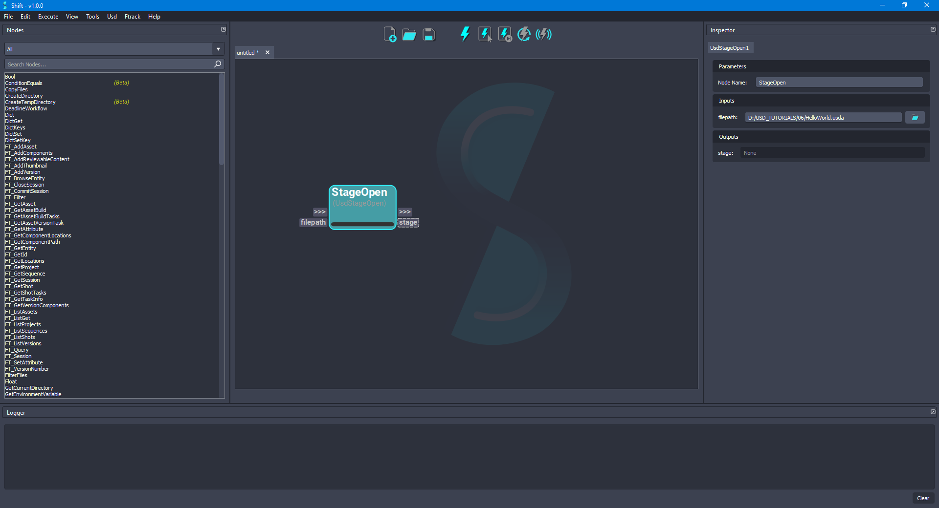
- Add a new UsdStageOpen node to the board and rename it to StageOpen. Using the Inspector widget, set as the value for the filepath input plug a filepath pointing to the
HelloWorld.usdafile downloaded for the example. The board should look like the following:
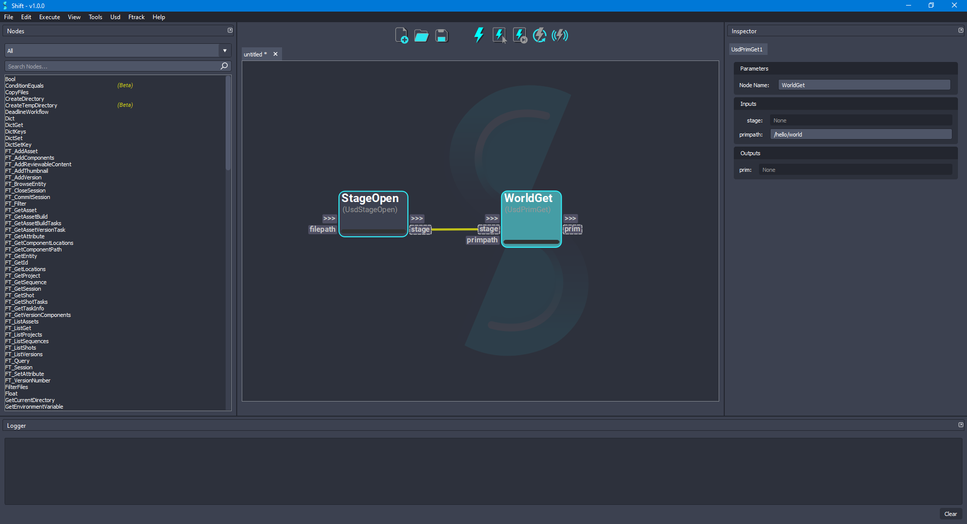
- Add a new UsdPrimGet node to the board and rename it to WorldGet. Connect the stage output plug from the StageOpen node to the stage input plug of the new node. Set
/hello/worldas the value to the primpath input plug. The board should look like the following:
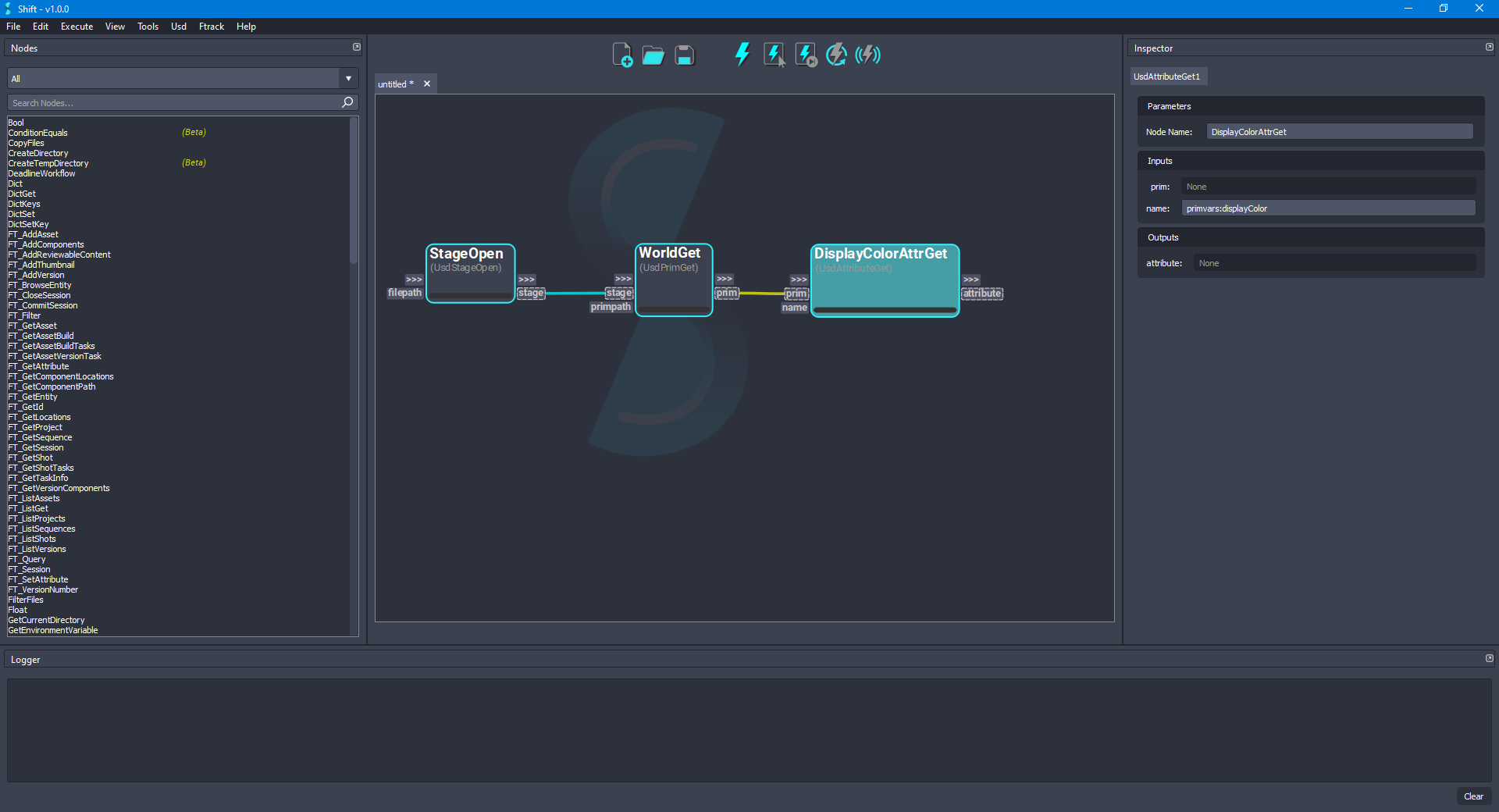
- Add a new UsdAttributeGet node to the board and rename it to DisplayColorAttrGet. Connect the prim output plug from the WorldGet node to the prim input plug of the new node. Set
primvars:displayColoras the value to the name input plug. The board should look like the following:
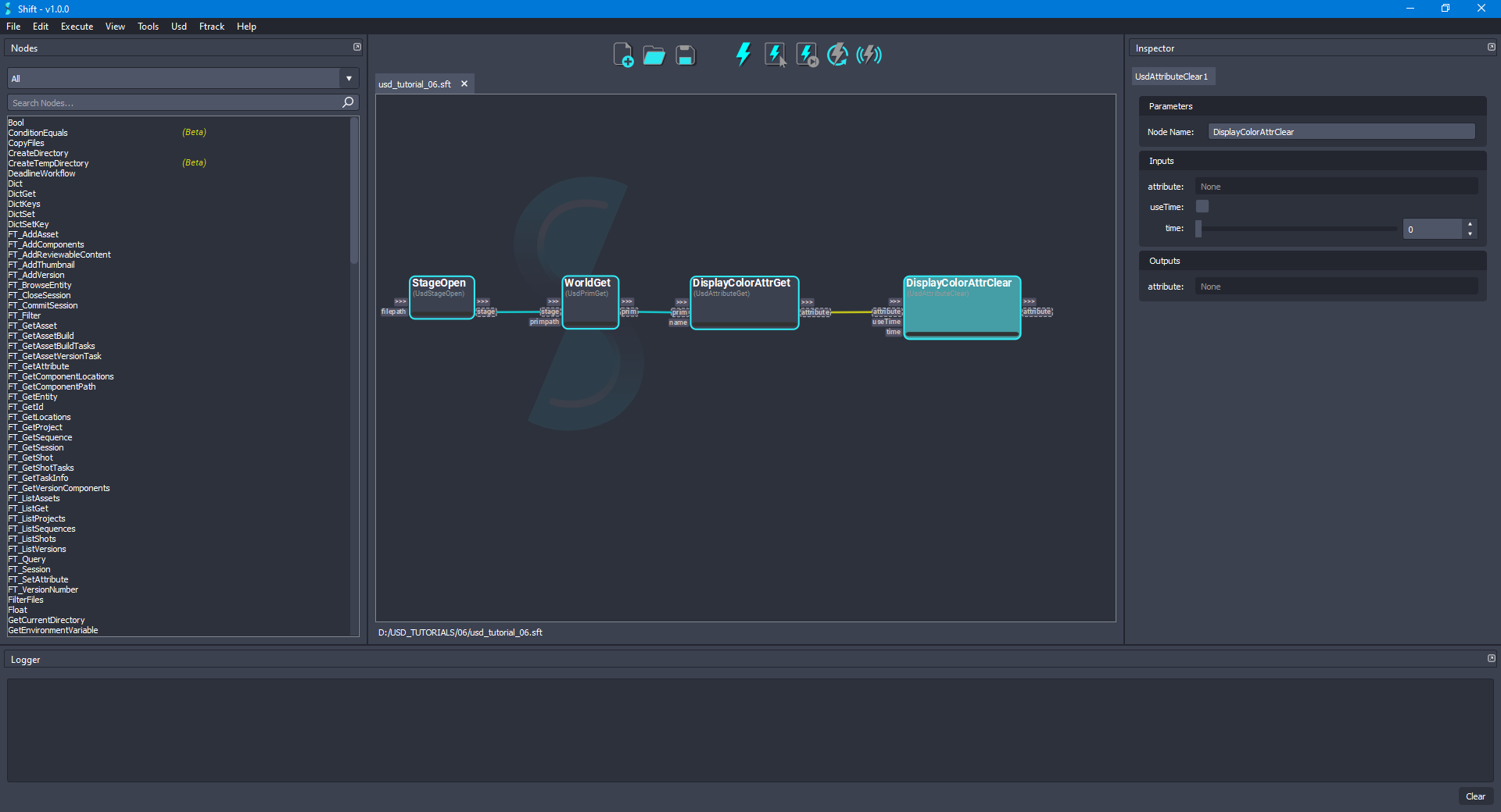
- For cleaning the authored value of the primvars:displayColor attribute, add a new UsdAttributeClear node to the board and rename it to DisplayColorAttrClear. Connect the attribute output plug from DisplayColorAttrGet node to the attribute input plug of the new node. Set the value
Falseto the useTime input plug and0as the value to the time input plug. The board should look like the following:
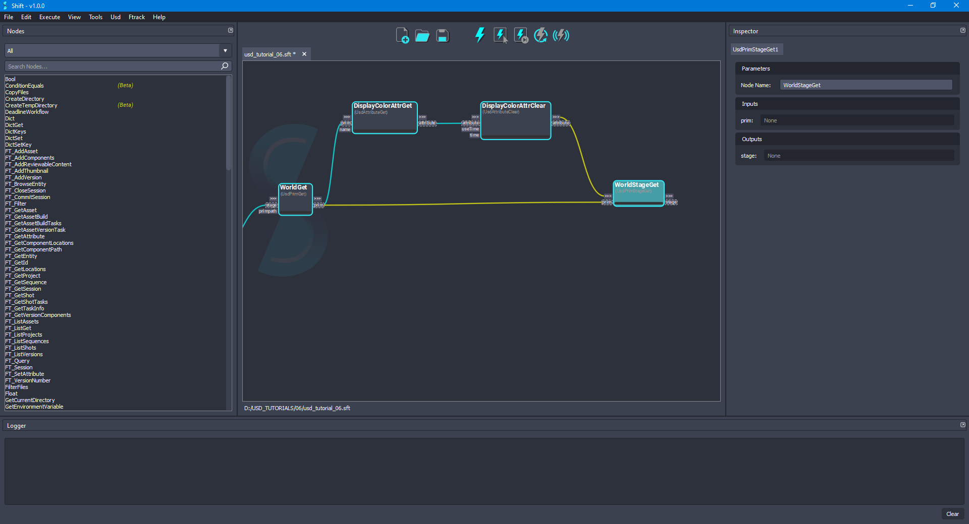
- Add a new UsdPrimStageGet node to the board and rename it to WorldStageGet. Connect the prim output plug from the WorldGet node to the prim input plug of the new node. The board should look like the following:
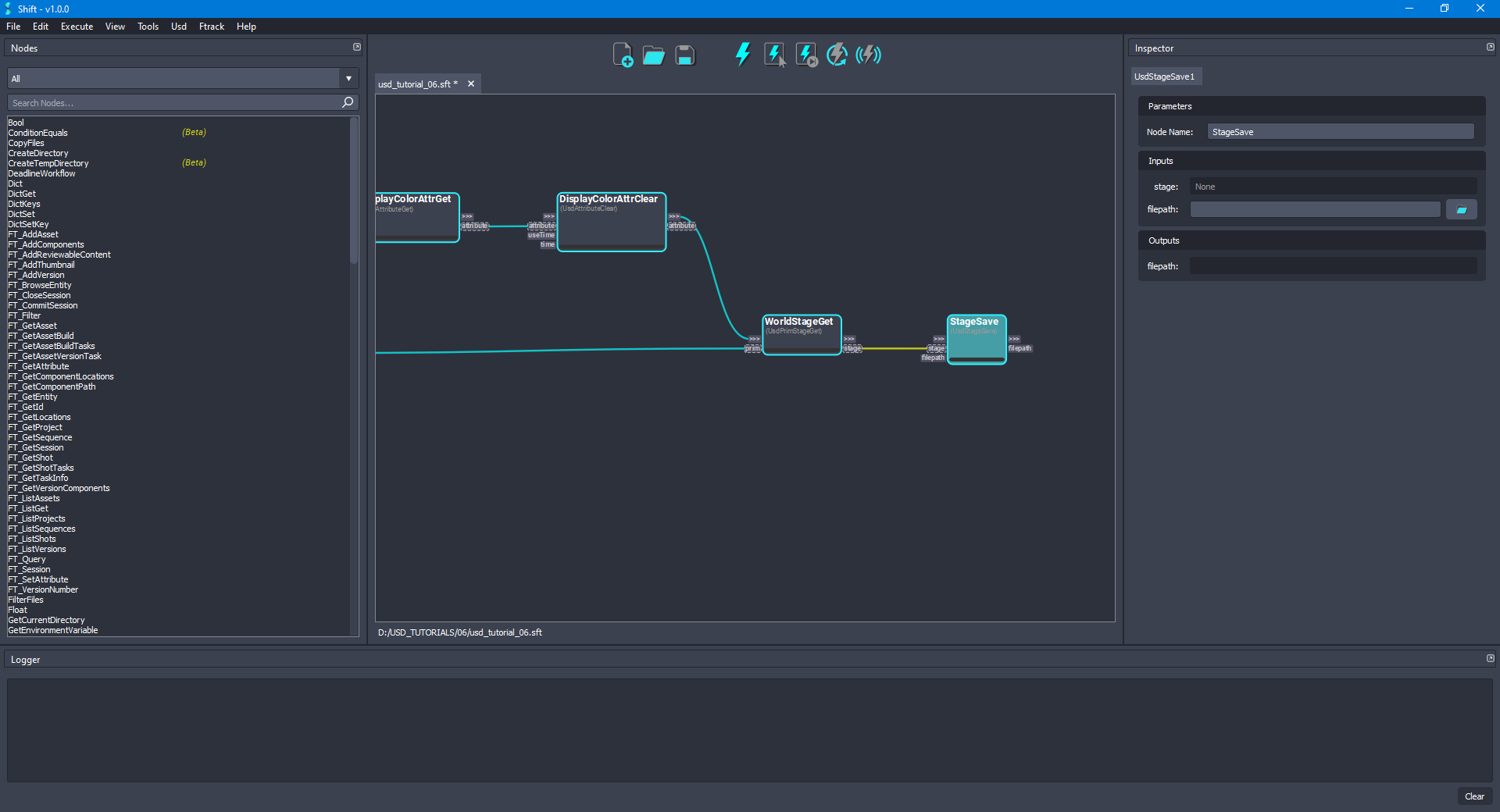
- For saving the modifications done to the
HelloWorld.usdafile, add a new UsdStageSave node to the board and rename it to StageSave. Connect the stage output plug from the WorldStageGet node to the stage input plug of the new node. Leave empty the value for the filepath input plug, doing this, the original file will be overridden. The board should look like the following:
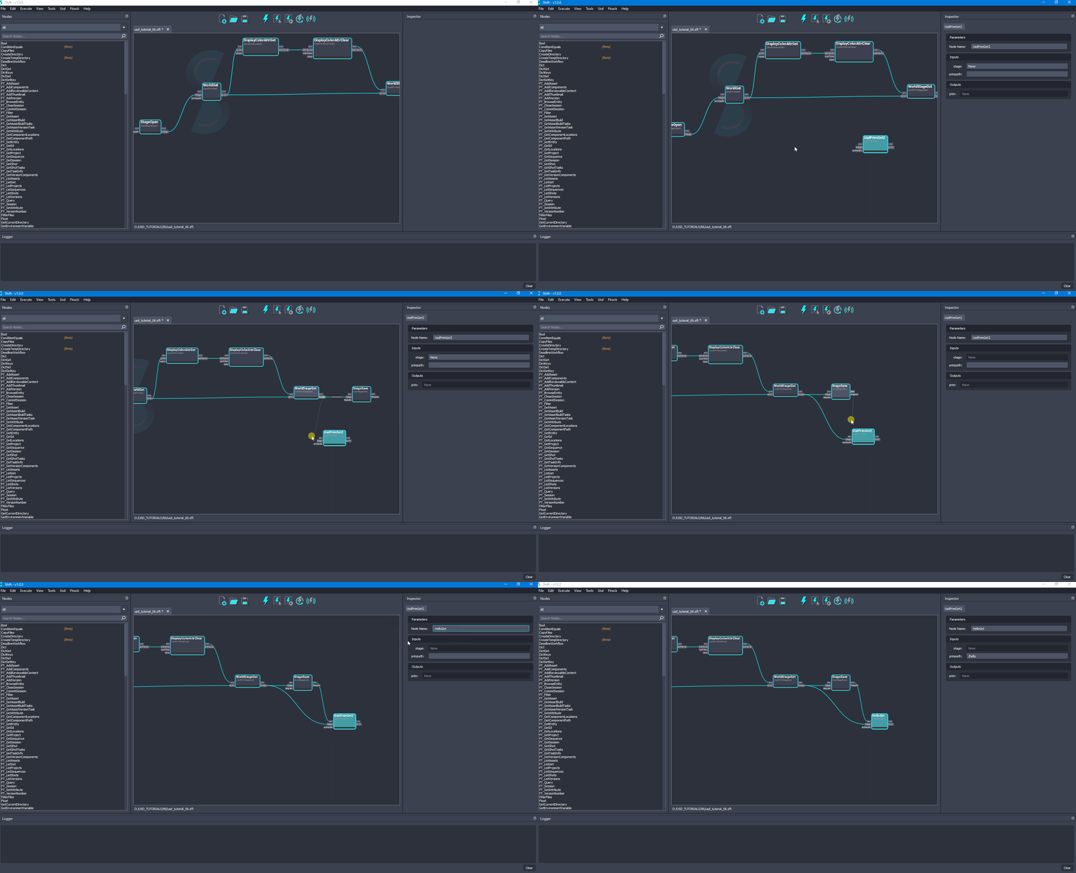
- Add a new UsdPrimGet node to the board and rename it to HelloGet. Connect the stage output plug from WorldStageGet node to the stage input plug of the new node, also, connect the out-trigger output plug from the StageSave node to the in-trigger input plug. Set
/helloas the value to the primpath input plug. The board should look like the following:
- Add a new UsdVariantSetAdd node to the board and rename it to ShadingVariantSetAdd. Connect the prim output plug from the HelloGet node to the prim input plug of the new node and set
shadingVariantas the value for the variantSetName input plug. The board should look like the following:
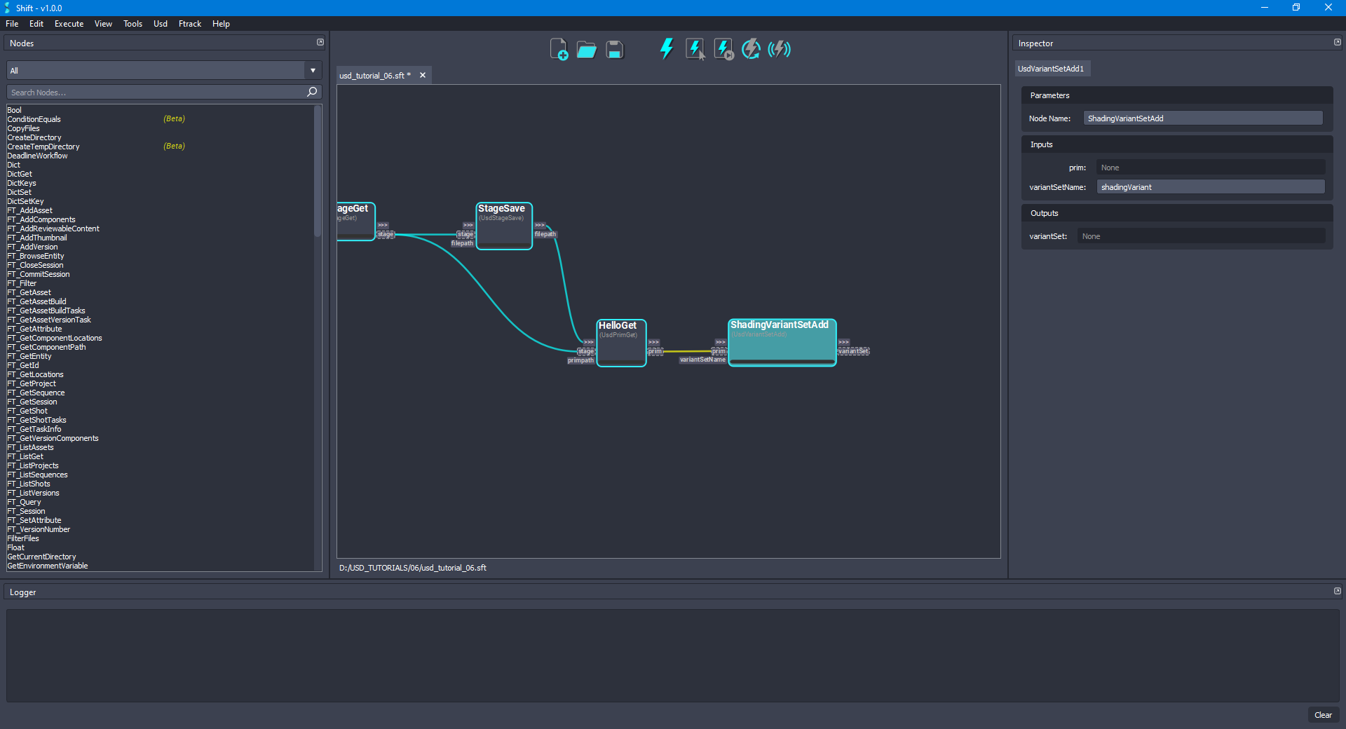
- For adding the variants to the new variant set, add a new UsdVariantAdd node and rename it to RedVariantAdd. Connect the variantSet output plug from the ShadingVariantSetAdd node to the variantSet input plug of the new node and set
redas the value for the variantName input plug. The board should look like the following:
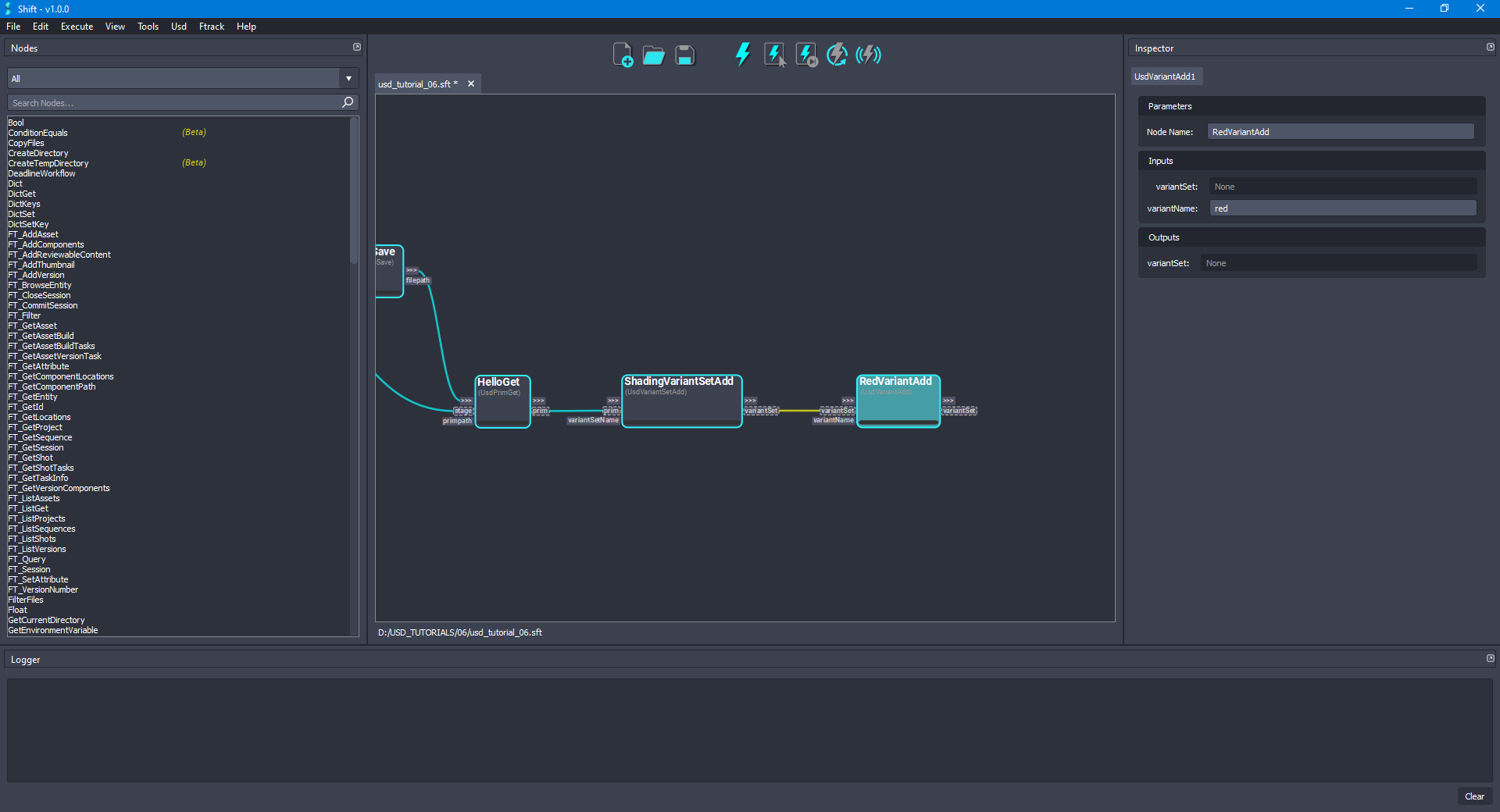
- As done in the previous step, add another UsdVariantAdd node and rename it to BlueVariantAdd. Connect the variantSet output plug from the RedVariantAdd node to the variantSet input plug of the new node and set
blueas the value for the variantName input plug. The board should look like the following:
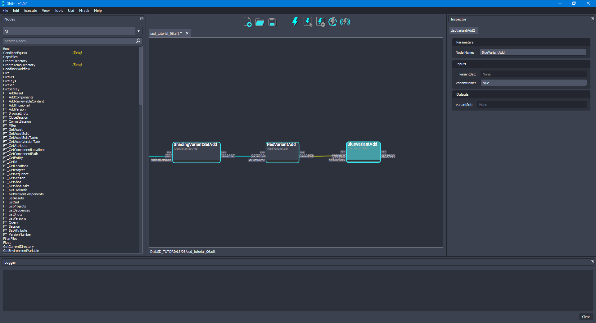
- As done in the previous step, add another UsdVariantAdd node and rename it to GreenVariantAdd. Connect the variantSet output plug from the BlueVariantAdd node to the variantSet input plug of the new node and set
greenas the value for the variantName input plug. The board should look like the following:
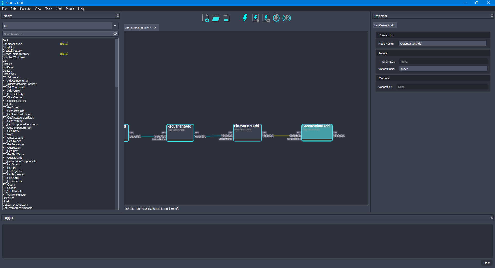
- Add a new UsdVariantSetSelected node and rename it to GreenVariantSelect. Connect the variantSet output plug from the GreenVariantAdd node to the variantSet input plug of the new node and set
greenas the value for the variantName input plug. The board should look like the following:
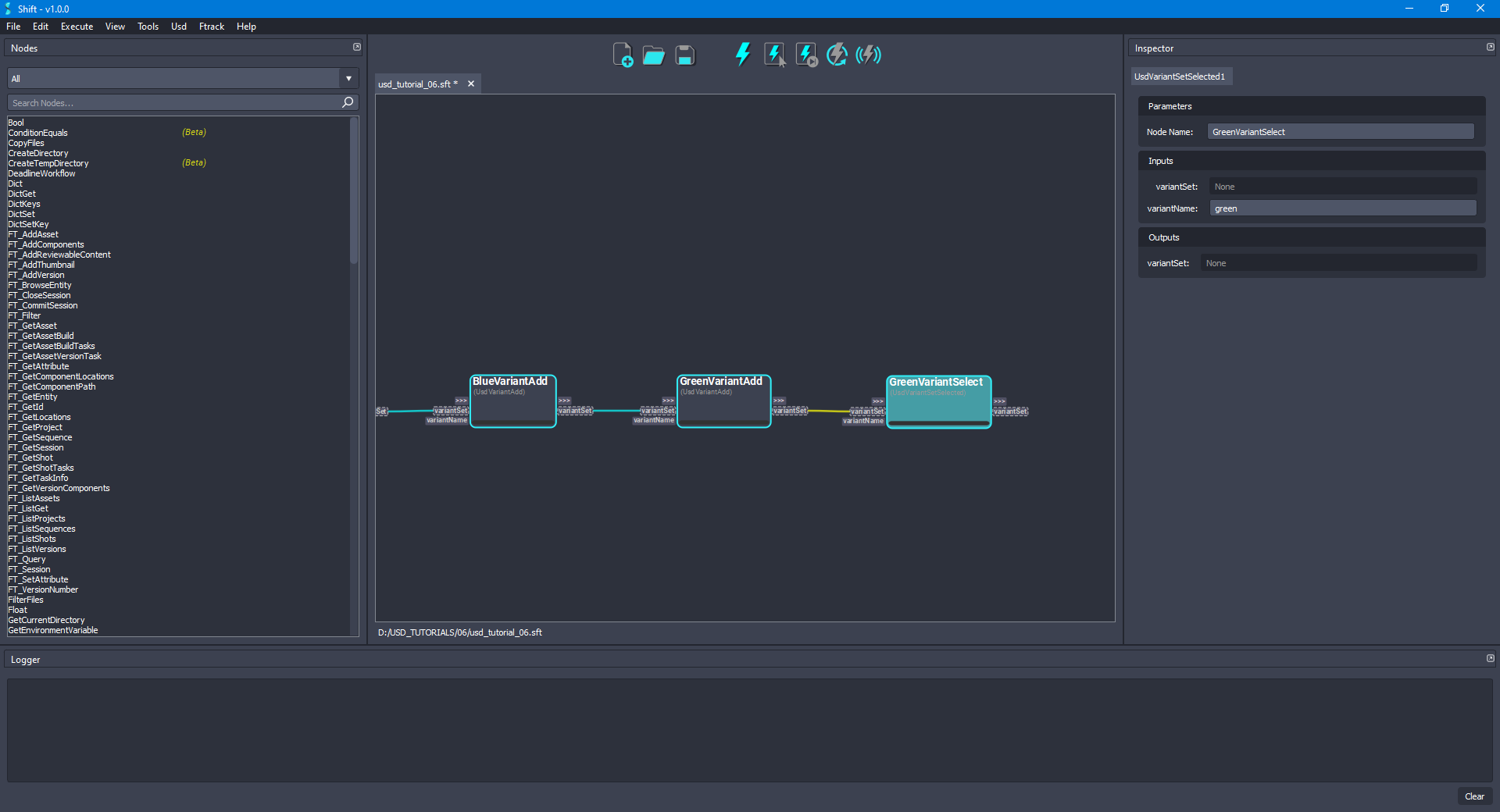
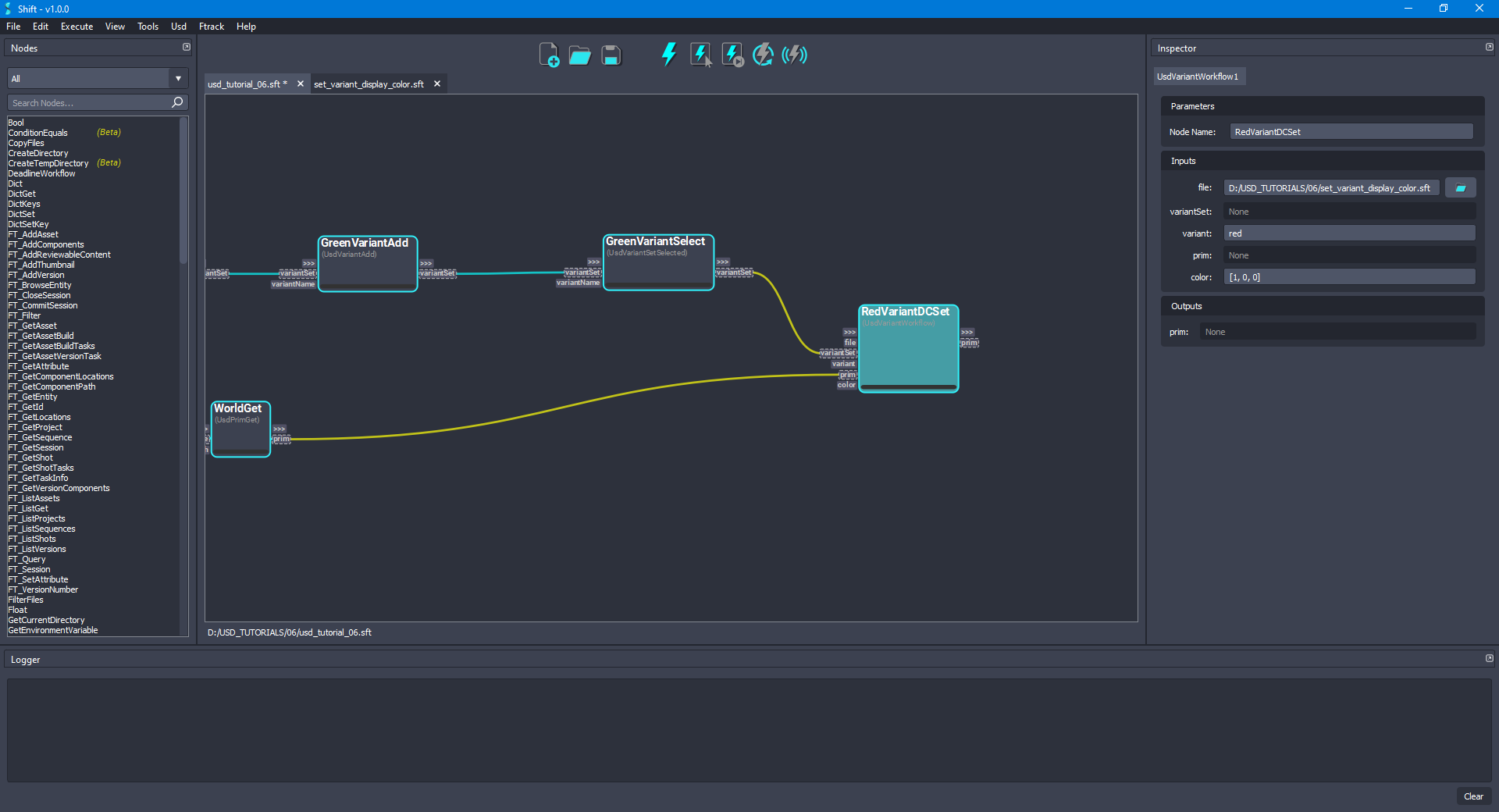
- Follow the steps done in the section Creating a variant workflow and add a new UsdVariantWorkflow node and rename it to RedVariantDCSet. Set the path to the workflow created in the Creating a variant workflow section as the value for the file input plug of the node, which should be named
set_variant_display_color.sft. Once the file is properly set, the node will be automatically updated to show the inputs and outputs from the nested workflow. Then, connect the variantSet output plug from the GreenVariantSelect node to the variantSet input plug of the new node, also, connect the prim output plug from the WorldGet node to the prim input plug of the new node. Setredas the value for the variant input plug and[1,0,0]as the value of the color input plug. The board should look like the following:
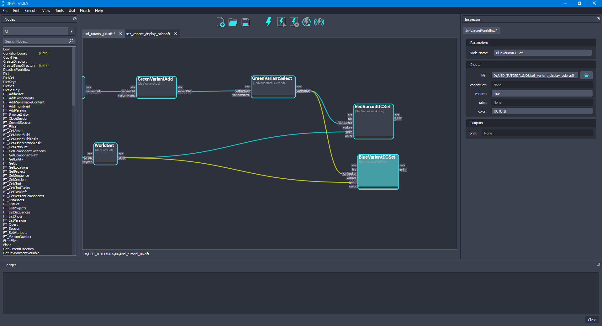
- Duplicate the RedVariantDCSet node and rename it as BlueVariantDCSet. As done before, connect the variantSet output plug from the BlueVariantSelect node to the variantSet input plug of the new node, also, connect the prim output plug from the WorldGet node to the prim input plug of the new node. Set
blueas the value for the variant input plug and[0,0,1]as the value of the color input plug. The board should look like the following:
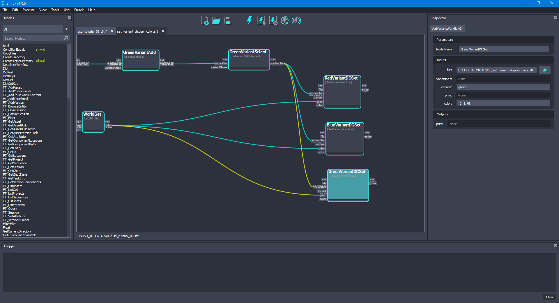
- Duplicate the RedVariantDCSet node again and rename it as GreenVariantDCSet. As done before, connect the variantSet output plug from the GreenVariantSelect node to the variantSet input plug of the new node, also, connect the prim output plug from the WorldGet node to the prim input plug of the new node. Set
greenas the value for the variant input plug and[0,1,0]as the value of the color input plug. The board should look like the following:
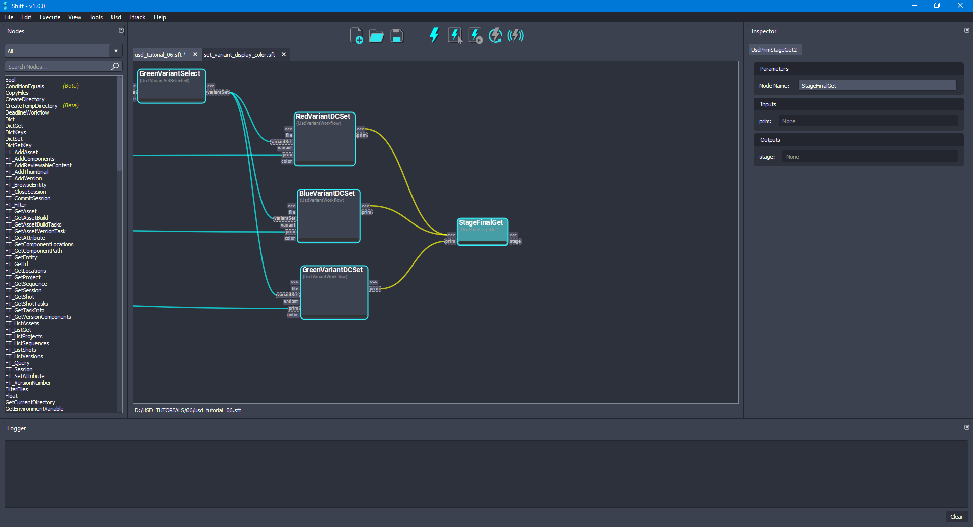
- Add a new UsdPrimStageGet node and rename it to StageFinalGet. Connect the prim output plug from the GreenVariantDCSet node to the prim input plug of the new node. Then, connect the out-trigger output plug from the RedVariantDCSet and BlueVariantDCSet nodes to the in-trigger input plug of the new node. The board should look like the following:
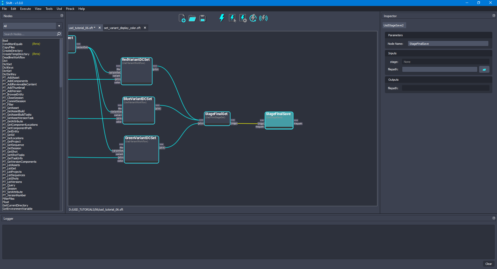
- Finally, to save the modifications done in the stage, add a new UsdStageSave node and rename it to StageFinalSave. Connect the stage output plug from the StageFinalGet node to the stage input plug of the new node. Leave empty the value for the filepath input plug, doing this, the original file will be overridden. The board should look like the following:
- Execute the workflow, the
HelloWorld.usdashould appear as modified containing the latest changes for the variants.
¶Creating a variant workflow
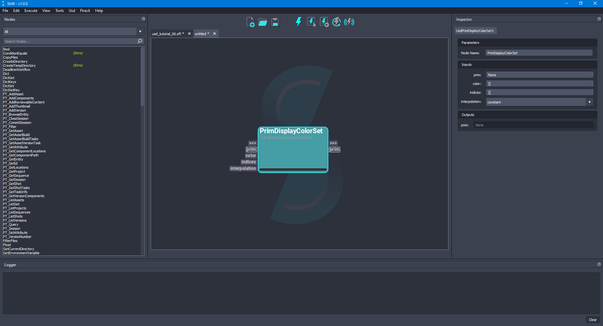
- In a new workflow, add a new UsdPrimDisplayColorSet node to the board and rename it to PrimDisplayColorSet. The board should look like the following:
- Now, add a new Input node to the board and rename it to Input. Drag and drop the connection from the PrimDisplayColorSet node's prim input plug over the Input node, using the Add Plug dialog, use the preselected options for creating the new plug. Repeat the same steps for the color input plug from the PrimDisplayColorSet node, creating the plug with the default selected values in the Add Plug dialog. The board should look like the following:
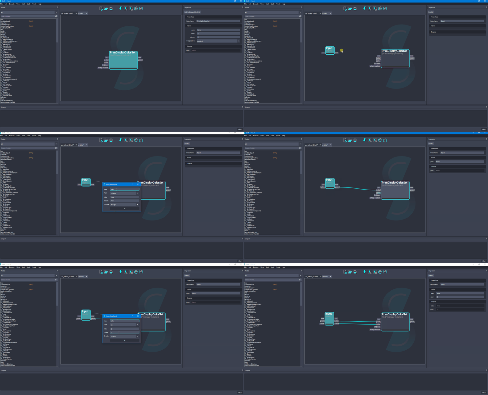
- Finally, add a new Output node to the board and rename it to Output. Drag and drop the connection from the PrimDisplayColorSet node's prim output plug over the Output node, using the Add Plug dialog, use the preselected options for creating the new plug. The board should look like the following:
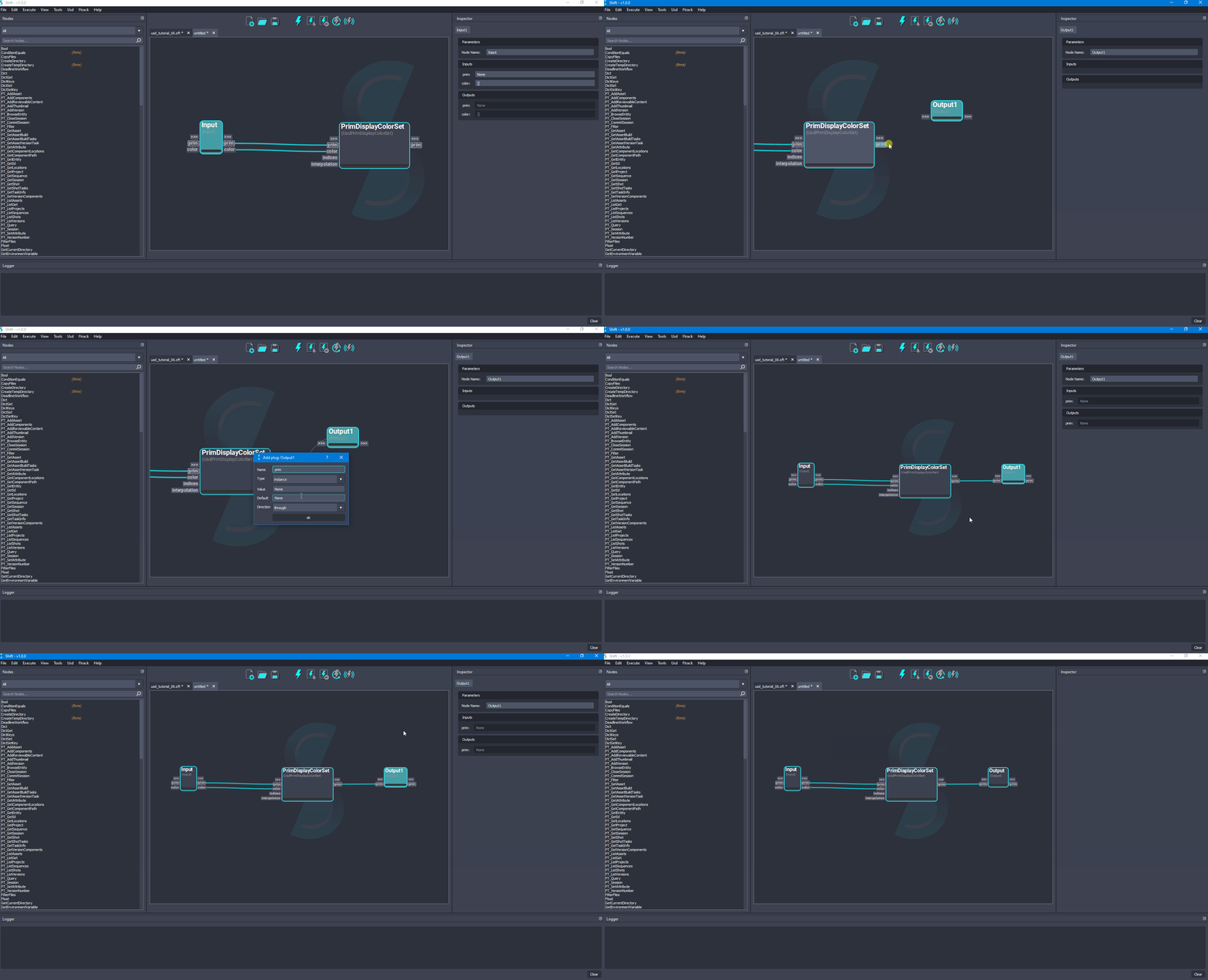
- Save the workflow with a proper name like
set_variant_display_color.sft. This workflow will be reused for the main workflow driving the example.
¶Visualising the Stage
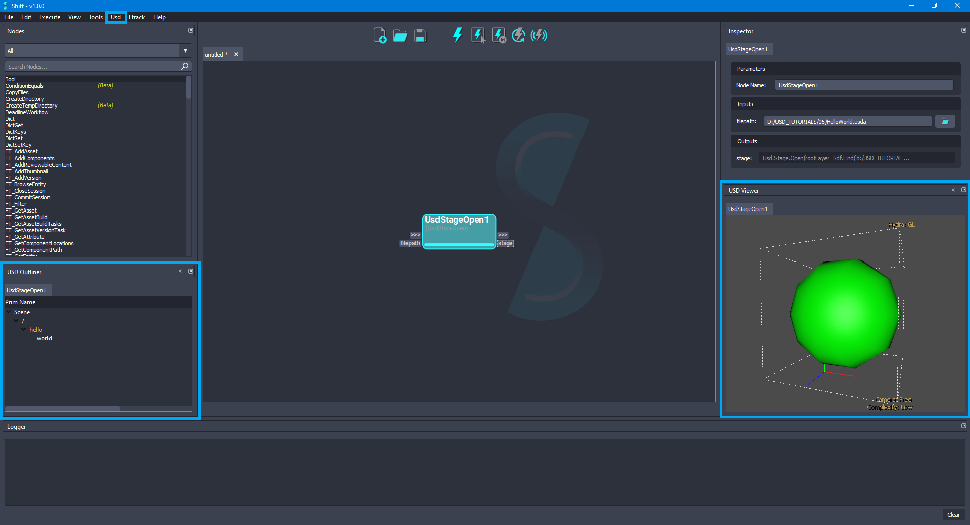
Shift is shipped with native plugins to visualise and inspect the stage. They can be accessed from the USD top menu:
-
USD Outliner: Shows the user the stage hierarchy sourced from specific Usd nodes in the active board workflow.
-
USD Viewer: Shows the stage in the USD viewer sourced from specific USD nodes in the active board workflow.
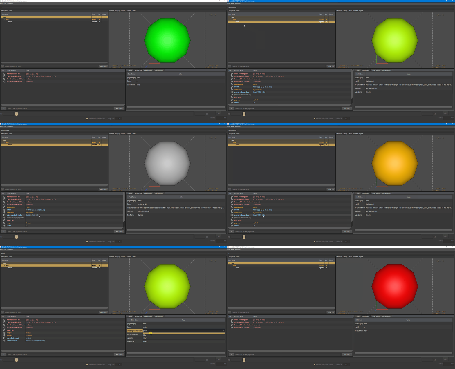
The USD viewer tool shipped with USD is used to visualise and inspect the stage viewport:
¶Workflow Resources
The workflows corresponding to this tutorial can be found in the following path in the Shift installation folder: <path_to_the_shift_installation_folder>/shift/examples/USD/tutorials/tutorial_06_authoring_variants/
< Traversing a Stage Main USD Tutorials Page >


