AdnFat is a Houdini SOP for fat tissue simulation. Thanks to a combination of volume, shape preservation and hard constraints, this SOP can produce dynamics that allow the fat geometry to produce realistic jiggle-like dynamics.
The inputs to the SOP are two geometries coherent in terms of number of vertices and triangulation. The first one is the geometry to be simulated (i.e. the fat geometry to simulate), while the second one is a deformed geometry which works as base mesh to drive the simulation (e.g. the simulated fascia). Given these two compatible surfaces, the solver procedurally constructs a volumetric internal structure between them. This structure is then simulated by computing: 1) volume constraints to make it resistant to compression and expansion; 2) volume shape preservation constraints to make the internal volume resistant to deformation; 3) hard constraints to attach the borders of the mesh to the base mesh; and 4) shape preservation constraints to preserve the original shape between connected vertices.
The AdnFat SOP is easy to create and configure in Houdini. The solver requires two input geometries that represent the inner and outer layers of the fat tissue. Typically, the inner layer corresponds to the simulated fascia, while the outer layer corresponds to the actual fat mesh to simulate. The inner layer works as a base mesh that the outer fat layer has to follow.
An AdnFat setup requires the following inputs:
Base Mesh (B): Mesh to drive the simulation mesh (e.g. the simulated fascia geometry).
Fat Mesh (F): Mesh to apply the AdnFat onto (e.g. the fat geometry).
NOTE
B and F must have the same vertex count and triangulation.
Both, B and F must be connected to the AdnFat SOP, otherwise the Fat solver will abort the simulation and the node will display an error.
The process to create an AdnFat is:
Go to the geometry context of the rig containing the base and fat meshes.
Press TAB and navigate to the submenu AdonisFX > Solvers to find the AdnFat SOP type.
Create it and connect the fat geometry to the first input and the base geometry to the second input.
The AdnFat is now ready to simulate using the default settings. Refer to the next section to customize their configuration.
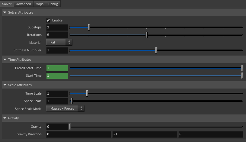
Number of steps that the solver will execute per simulation frame. Greater values mean greater computational cost. Has a range of [1, 10]. The upper limit is soft, higher values can be used.
Iterations
Integer
5
✓
Number of iterations that the solver will execute per simulation step. Greater values mean greater computational cost. Has a range of [1, 10]. The upper limit is soft, higher values can be used.
Material
Enumerator
Fat
✓
Solver stiffness presets per material. The materials are listed from lowest to highest stiffness. There are 8 different presets: Fat: 103, Muscle: 5e3, Rubber: 106, Tendon: 5e7, Leather: 108, Wood: 6e9, Skin: 12e3.
Stiffness Multiplier
Float
1.0
✓
Multiplier factor to scale up or down the material stiffness. Has a range of [0.0, 2.0]. The upper limit is soft, higher values can be used.
Sets the scaling factor applied to the simulation time step. Has a range of [0.0, 2.0]. The upper limit is soft, higher values can be used.
Space Scale
Float
1.0
✓
Sets the scaling factor applied to the masses and/or the forces (e.g. gravity). AdonisFX interprets the scene units in centimeters. If modeling your creature you apply a scaling factor for whatever reason (e.g. to avoid precision issues in Houdini), you will have to adjust for this scaling factor using this attribute. If your character is supposed to be 170 units tall, but you prefer to model it to be 17 units tall, then you will need to set the space scale to a value of 10. This will ensure that your 17 units creature will simulate as if it was 170 units tall. Has a range of [0.0, 2.0]. The upper limit is soft, higher values can be used.
Space Scale Mode
Enumerator
Masses + Forces
✓
Determines if the spatial scaling affects the masses, the forces, or both. The available options are:
Masses: The Space Scale only affects masses.
Forces: The Space Scale only affects forces.
Masses + Forces: The Space Scale affects masses and forces.
Sets the magnitude of the gravity acceleration in m/s2. The value is internally converted to cm/s2. Has a range of [0.0, 100.0]. The upper limit is soft, higher values can be used.
Gravity Direction
Float3
{0.0, -1.0, 0.0}
✓
Sets the direction of the gravity acceleration. Vectors introduced do not need to be normalized, but they will get normalized internally.
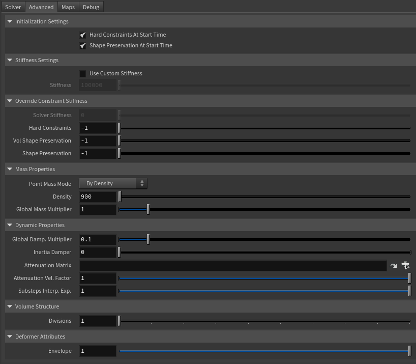
Flag that forces the hard constraints to reinitialize at start time. This attribute has effect only if preroll start time is lower than start time.
Shape Preservation At Start Time
Boolean
True
✗
Flag that forces the shape preservation constraints to reinitialize at start time. This attribute has effect only if preroll start time is lower than start time.
Stiffness Settings
Name
Type
Default
Animatable
Description
Use Custom Stiffness
Boolean
False
✓
Toggles the use of a custom stiffness value. If custom stiffness is used, Material and Stiffness Multiplier will be disabled and Stiffness will be used instead.
Stiffness
Float
105
✓
Sets the custom stiffness value. Its value must be greater than 0.0.
Override Constraint Stiffness
Name
Type
Default
Animatable
Description
Solver Stiffness
Float
0.0
✗
Shows the global stiffness value currently used by the solver.
Hard Constraints
Float
-1.0
✓
Sets the stiffness override value for hard constraints. If the value is less than 0.0, the global stiffness will be used. Otherwise, this custom stiffness will override the global stiffness. Has a range of [0.0, 1012]. The upper limit is soft, higher values can be used.
Volume Shape Preservation
Float
-1.0
✓
Sets the stiffness override value for the volume shape preservation constraints. If the value is less than 0.0, the global stiffness will be used. Otherwise, this custom stiffness will override the global stiffness. Has a range of [0.0, 1012]. The upper limit is soft, higher values can be used.
Shape Preservation
Float
-1.0
✓
Sets the stiffness override value for the shape preservation constraints. If the value is less than 0.0, the global stiffness will be used. Otherwise, this custom stiffness will override the global stiffness. Has a range of [0.0, 1012]. The upper limit is soft, higher values can be used.
NOTE
Providing a stiffness override value of 0.0 will disable the computation of that constraint.
Mass Properties
Name
Type
Default
Animatable
Description
Point Mass Mode
Enumerator
By Density
✓
Defines how masses should be used in the solver.
By Density allows to estimate the mass value by multiplying Density * Area.
By Uniform Value allows to set a uniform mass value.
Density
Float
900.0
✓
Sets the density value in kg/m3 to be able to estimate mass values with By Density mode. The value is internally converted to g/cm3. Has a range of [0.001, 106]. Lower and upper limits are soft, lower and higher values can be used.
Global Mass Multiplier
Float
1.0
✓
Sets the scaling factor applied to the mass of every point. Has a range of [0.001, 10.0]. Lower and upper limits are soft, lower and higher values can be used.
Dynamic Properties
Name
Type
Default
Animatable
Description
Global Damping Multiplier
Float
0.1
✓
Sets the scaling factor applied to the global damping of every point. Has a range of [0.0, 1.0]. The upper limit is soft, higher values can be used.
Inertia Damper
Float
0.0
✓
Sets the linear damping applied to the dynamics of every point. Has a range of [0.0, 1.0]. The upper limit is soft, higher values can be used.
Attenuation Matrix
String
✓
Object path of the node to extract the transformation matrix from to compute the velocity attenuation.
Attenuation Velocity Factor
Float
1.0
✓
Sets the weight of the attenuation applied to the velocities of the simulated vertices driven by the Attenuation Matrix. Has a range of [0.0, 1.0]. The upper limit is soft, higher values can be used.
Substeps Interp. Exp.
Float
1.0
✓
Sets the exponential factor to weight the interpolation at each substep. Has a range of [0.0, 1.0]. The upper limit is soft, higher values can be used. A value of 0.0 disables the interpolation: base geometry and attenuation matrix are not interpolated. A value of 1.0 applies linear interpolation (base geometry and attenuation matrix) between previous and current frame based on a linear weight, i.e. weight = substep / num_substeps. A value between 0.0 and 1.0 applies exponential interpolation (base geometry and attenuation matrix) between previous and current frame based on an exponential weight, i.e. weight = (substep / num_substeps) ^ exponent.
Volume Structure
Name
Type
Default
Animatable
Description
Divisions
Integer
1
✗
Sets the number of divisions to create in the internal volume. The lower this value is, the faster the solver computes. Has a range of [1, 10]. The upper limit is soft, higher values can be used.
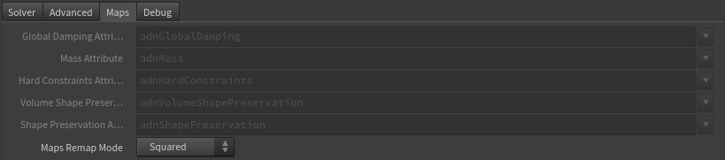
Specifies the name of the per-point attribute to read the global damping from. The expected attribute name is adnGlobalDamping. The expected range of the per-point values is [0.0, 1.0].
Mass Attribute
float
1.0
✗
Specifies the name of the per-point attribute to read the mass values from. The expected attribute name is adnMass. The expected range of the per-point values is [0.001, 1.0].
Hard Constraints Attribute
float
0.0
✗
Specifies the name of the per-point attribute to read the hard constraints values from. The expected attribute name is adnHardConstraints. The expected range of the per-point values is [0.0, 1.0].
Volume Shape Preservation Attribute
float
1.0
✗
Specifies the name of the per-point attribute to read the volume shape preservation values from. The expected attribute name is adnVolumeShapePreservation. The expected range of the per-point values is [0.0, 1.0].
Shape Preservation Attribute
float
1.0
✗
Specifies the name of the per-point attribute to read the shape preservation values from. The expected attribute name is adnShapePreservation. The expected range of the per-point values is [0.0, 1.0].
Maps Remap Mode
Enumerator
Squared
✗
Defines the mode of remapping the painted values of volume shape preservation, shape preservation and hard constraints. The other paintable maps remain unmodified. Each remap mode applies a function to the input painted values (x) to get the final value used for the simulation (y).
Linear: y = x
Squared: y = x^2
Cubic: y = x^3
Square Root: y = x^(1/2)
Cube Root: y = x^(1/3)
Logarithmic: y = log((exp(1) - 1) * x + 1)
NOTE
All maps parameters are disabled in the Maps tab because the attribute names are fixed to drive specific functionalities of the solver.
Fixed point attribute names also ensure compatibility with the API.
To copy the map names of the disabled attributes for painting (using an attribute paint node) right click on the disabled map attribute parameter, press "Copy Parameter", select the attribute paint node and on the attribute name entry right click and press "Paste Values". This allows to easily copy the attribute name for painting.
The Make Paintable utility provided in the AdonisFX menu > Utils, can be used to create the attribpaint node and automatically populate the entries with the map names of the AdnFat SOP.
If a point attribute on the geostream does not match the naming convention exposed in the node, use an "Attribute Rename" node to rename the attribute to match the expected naming convention.
In order to provide more artistic control, some key parameters of the AdnFat solver are exposed as paintable attributes in the SOP. The maps are point attributes that must be present in the geometry stream injected into the SOP. For that, the Houdini attribpaint node can be used.
Name
Default
Description
Global Damping
1.0
Set global damping per vertex in the simulated mesh. The greater the value per vertex is the more damping of velocities.
Hard Constraints
0.0
Weight to modulate the correction applied to the vertices and the internal virtual points to keep them at a constant transformation, local to the closest point on the base mesh at initialization. Hard Constraint maps will force the points to keep the original position.
Tip: In most of the cases this map is flooded to 0.0.
Tip: Only if the volume between the fat mesh and the base mesh on the edges is big (e.g. wrists, ankle, neck) then it might be useful to paint a value of 1.0 in those areas.
Tip: Smooth the borders by using the Smooth and Flood combination to make sure that there are no discontinuities in the weights map. This will help the simulation to not produce sharp differences in the dynamics of every vertex compared to its connected vertices.
Masses
1.0
Multiplier to the individual mass values per vertex in the simulated volume.
Shape Preservation
1.0
Amount of correction to apply to a vertex to maintain the initial state of the shape formed with the surrounding vertices.
Volume Shape Preservation
1.0
Amount of correction to apply to the volume structure to preserve the initial volumetric shape and prevent it from distortion.
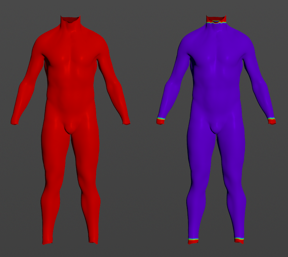
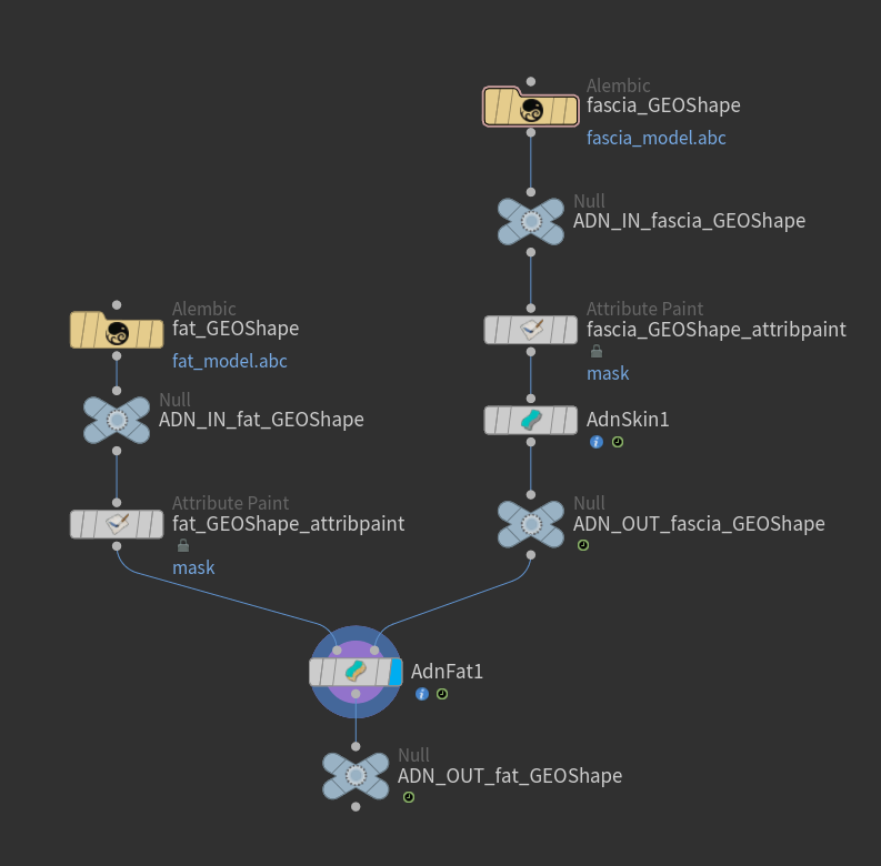
Figure 5: Example of painted weights on the fat layer: on the left the map is flooded to 1.0 for global damping, mass, volume shape preservation and shape preservation; on the right the hard constraints map is painted to 1.0 on the extremities. Figure 6: Example of AdnFat network. Using null nodes with ADN_IN_ and ADN_OUT_ prefixes to encapsulate the AdonisFX deformable section is recommended to keep the network compatible with the API.
NOTE
To tweak the point attributes of an AdnFat SOP, an attribpaint is needed. To ease the creation and initial configuration of this node, select the AdnFat SOP and click on AdonisFX > Utils > Make Paintable. This utility will create an attribcreate node to define the required point attributes and assign their default values followed by an attribpaint node to allow these attributes to be modified. Both nodes are automatically named and properly connected to the AdnFat node.
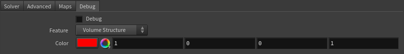
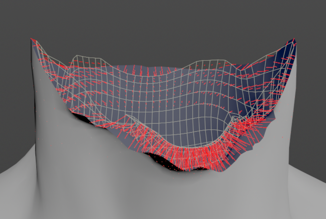
In order to better visualize deformer constraints and attributes in the Houdini viewport there is the option to enable the debugger, found in the switcher menu labeled Debug in the parameter interface. The visualization of the guide geometry is only activated when selecting the node to debug and cannot be enabled globally.
To enable the debugger the Debug checkbox must be marked. To select the specific feature you would like to visualize, choose it from the list provided in Features. The features that can be visualized with the debugger in the AdnFat deformer are:
Hard Constraints: For each vertex on the simulated mesh and each virtual point that belongs to an internal layer, a line will be drawn from the point to the corresponding closest point on the base mesh if its Hard Constraints weight is greater than 0.0.
Shape Preservation: For each vertex with a shape preservation weight greater than 0.0, a line will be drawn from each adjacent vertex to the opposite adjacent vertex.
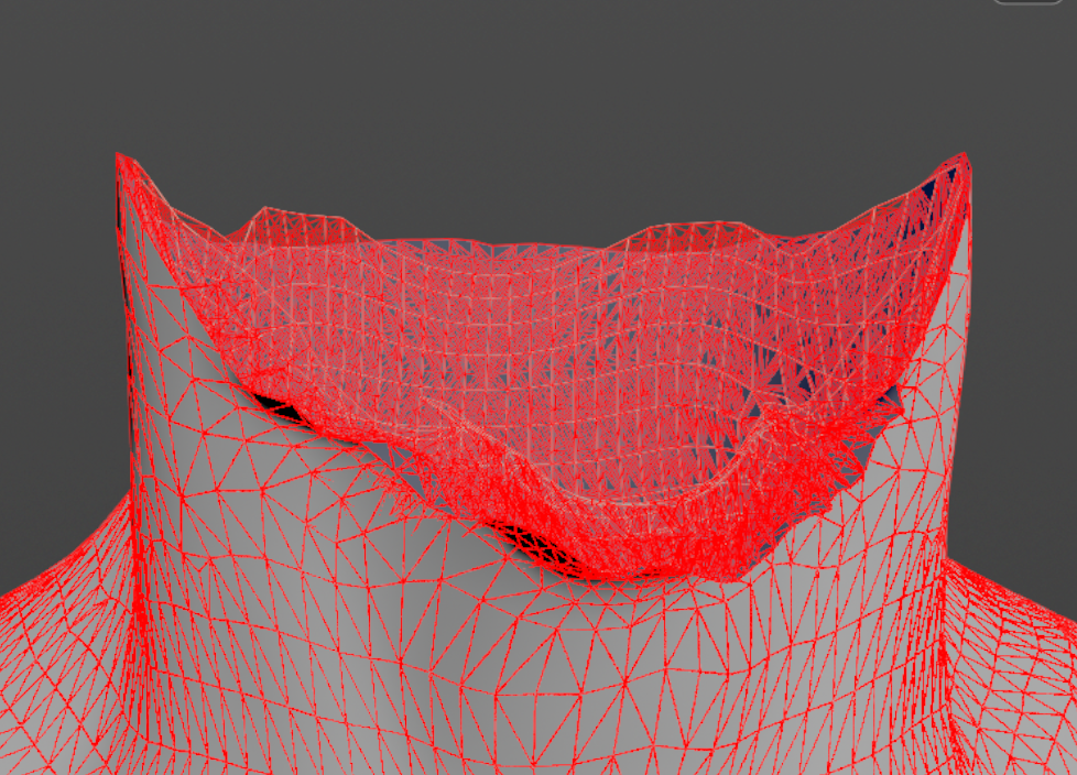
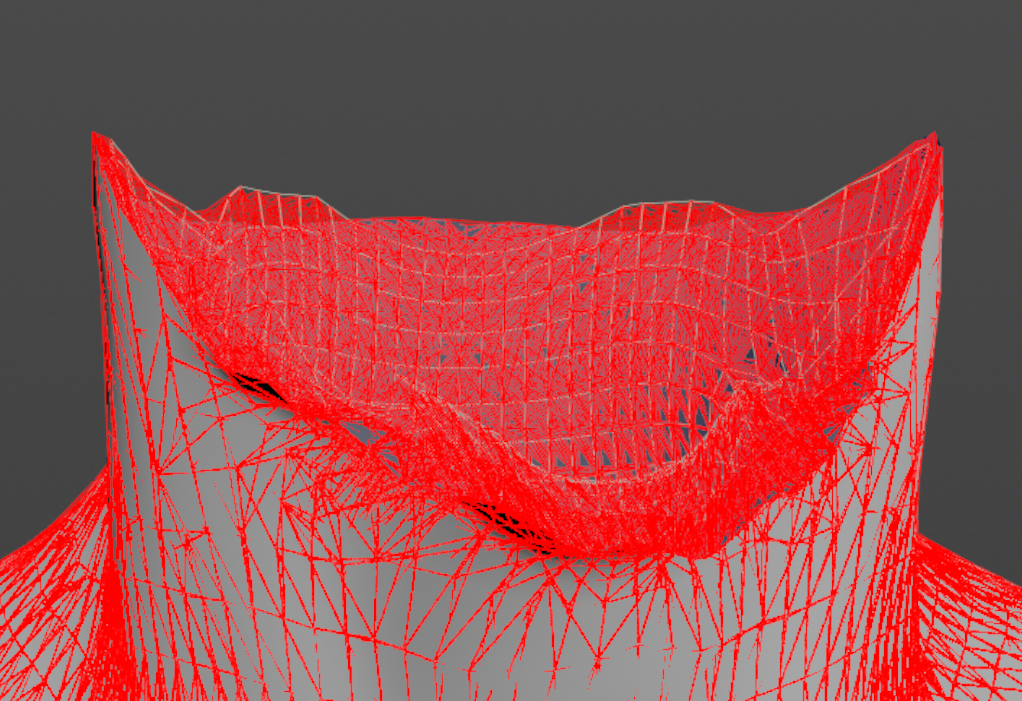
Volume Structure: A line will be drawn for every connection between two points in the volume. A point can be either a vertex on the base mesh, a vertex on the simulated fat mesh or a virtual point that belongs to an internal layer generated by the procedural construction based on the Divisions attribute.
Connections in AdonisFX for Houdini should be handled in two ways:
Detail expression: detail("/obj/geo1/L_adnLocatorRotation_armFlexionShape", "adnActivationRotation", 0) where the first component should contain an API compliant naming convention and the second the detail attribute name that some of the AdonisFX SOP nodes output. This should be used when the requirement is for the connected geometry to cook before retrieving the detail attribute. This could be used for example to drive a parameter of the node using the activation value output from a sensor/locator.
Channel expression: ch("../AdnMuscle1/envelope") where the first component should contain an API compliant naming convention and the second the referenced channel to the parameter name. This could be used to for example connect a float attribute to drive a parameter on the node.

 SOP type.