AdonisFX Sensors are nodes in charge of interpreting data extracted from transform nodes and compute information that can be fed into the deformers to alter their behavior. Sensors work in combination with Locators to display the computed information in an intuitive way using coloring. The sensors produce the results in two separated outputs: the raw value result of the evaluation of the input transform nodes (e.g. Out Angle); and the remapped value result of the evaluation of the raw value into the existing remap ramp attributes (e.g. Out Angle Remap). Thanks to this, the remapped values are already adjusted within a custom range of activation that will drive the coloring of the locators and the activation of an AdnMuscle for example.
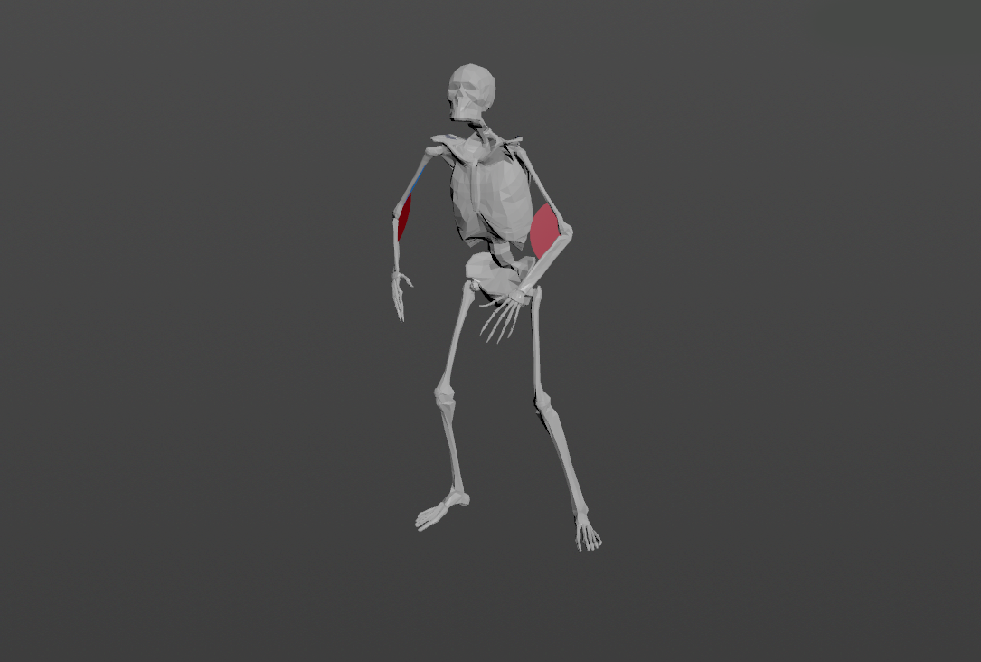
AdnSensorPosition is the sensor for computing meaningful output raw values representing the velocity or acceleration of a transform node. Additionally, the sensor remaps the values of velocity and acceleration to produce desirable activation values within a certain range to drive the simulation of an AdonisFX deformer. This sensor has to work in combination with an AdnLocatorPosition both for setup and visualization. An example use case for this sensor would be applying it to the wrist connection of an arm outputting velocities while swinging.
An AdnSensorPosition will be in charge of computing, remapping and feeding activation (or other) values into the AdnLocatorPosition for visualization purposes, which in turn feeds the AdonisFX deformers to drive the simulation. The value of the sensor can be used, for example, to drive the activation of a muscle simulating contraction to increase its stiffness.
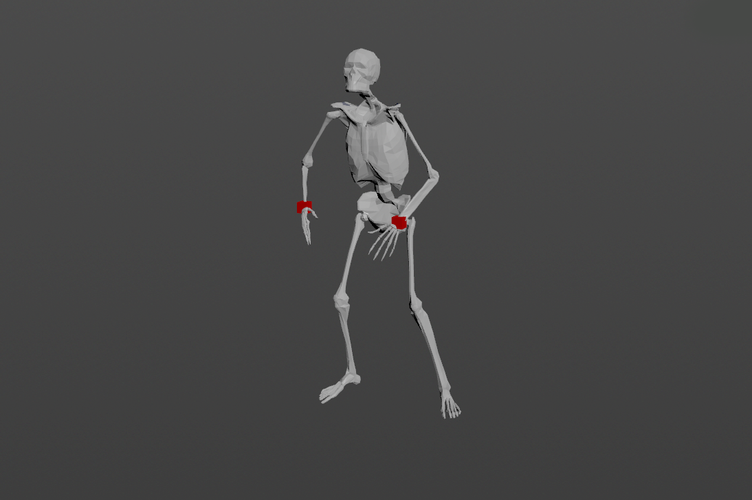
Figure 1: AdnSensorPosition used in a human model.
Only one transform will be required to create the AdnSensorPosition. To create an AdnSensorPosition and connect it to an existing AdnLocatorPosition:
Go to the geometry context of the rig containing the rig setup to which the sensors should be applied.
Press TAB and navigate to the submenu AdonisFX > Sensors to find the AdnSensorPosition SOP type.
Create it and connect the output of the AdnSensorPosition sensor to its corresponding AdnLocatorPosition input.
Go to the AdnSensorPosition's Input tab and select the transform nodes from which to extract the transformation from (e.g. joints, null nodes, rivets, etc). Use the "Operator Chooser" in the locator's UI to select the correct target node containing transform information. Generally these input nodes will be located on the /obj level as a null, joint or rivet.
The AdnSensorPosition is created and ready to be used with its corresponding AdnLocatorPosition.
Figure 2: AdnSensorPosition and AdnLocatorPosition in the node graph. The connection is created via detail expression to the AdnMuscle node.
NOTE
Activation values are output from the sensor nodes via detail attributes (adnActivationVelocity and adnActivationAcceleration). It is to note that these attribute names are expected by the locator nodes and their name should not be altered.
When connecting the sensors to a muscle or an activation node for example it is advisable to first connect the sensor to its corresponding locator and use the locator node as reference for creating the detail expression connection.
To create a connection to the muscle use a detail expression on the muscle's parameter (for example the activation parameter) in the form of: detail("/obj/geo1/AdnLocatorPosition1", "adnActivationVelocity", 0) pointing directly to the locator that is connected to the sensor. This will allow for the muscle nodes to pick up the detail activation attribute from the sensor connection.
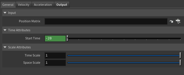
Matrix containing the position in world space of the transform node. This entry is an operator path pointing to nodes that contain transform information to drive the locator. These nodes are generally exposed on the /obj level.
Time Attributes
Name
Type
Default
Animatable
Description
Start Time
Time
Current frame
✗
Determines the frame at which the playback/simulation starts.
Scale Attributes
Name
Type
Default
Animatable
Description
Time Scale
Float
1.0
✓
Sets the scaling factor applied to the compute the velocity or acceleration. Has a range of [0.001, 10.0]. The upper limit is soft, higher values can be used.
Space Scale
Float
1.0
✓
Sets the scaling factor applied to velocity or acceleration. Has a range of [0.001, 100.0]. The upper limit is soft, higher values can be used.
Velocity Remap Settings
Name
Type
Default
Animatable
Description
Velocity Activation Attribute
float
0.0
✗
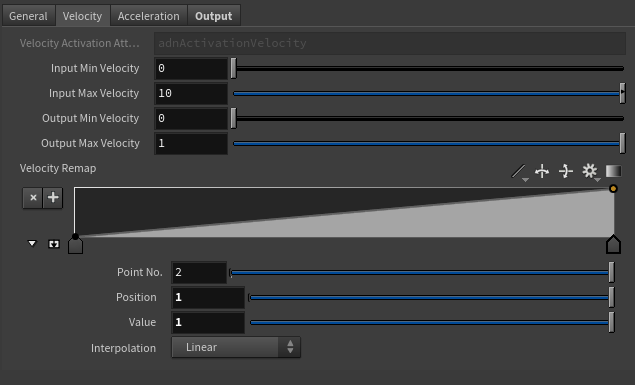
Specifies the name of the detail attribute that is used for exporting the remapped activation value. The expected attribute name is adnActivationVelocity.
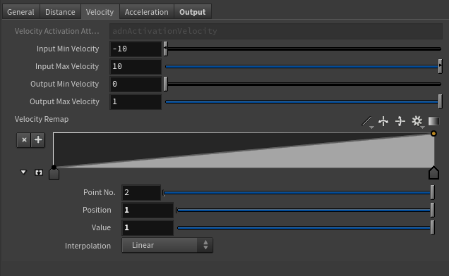
Input Min Velocity
Float
0.0
✓
Lower limit of the range used to map the Out Velocity value before evaluating it on the ramp attribute.
Input Max Velocity
Float
10.0
✓
Upper limit of the range used to map the Out Velocity value before evaluating it on the ramp attribute.
Output Min Velocity
Float
0.0
✓
Lower limit of the range used to map the value returned by the ramp attribute and calculate the final remapped velocity.
Output Max Velocity
Float
1.0
✓
Upper limit of the range used to map the value returned by the ramp attribute and calculate the final remapped velocity.
Selected Position
Float
0.0
✓
X-axis value of the ramp attribute.
Selected Value
Float
0.0
✓
Y-axis value of the ramp attribute.
Interpolation
Enumerator
Linear
✓
Interpolation method to be used between every two consecutive points in the ramp. There are seven options: Constant, Linear, Catmull-Rom, Monotone Cubic, Bezier, B-Spline, Hermite
Acceleration Remap Settings
Name
Type
Default
Animatable
Description
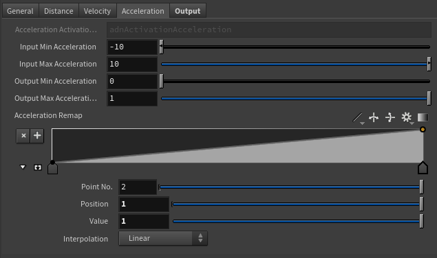
Acceleration Activation Attribute
float
0.0
✗
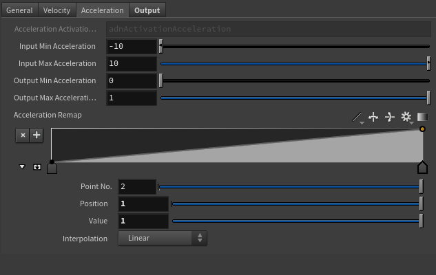
Specifies the name of the detail attribute that is used for exporting the remapped activation value. The expected attribute name is adnActivationAcceleration.
Selected Position
Float
0.0
✓
X-axis value of the ramp attribute.
Selected Value
Float
0.0
✓
Y-axis value of the ramp attribute.
Interpolation
Enumerator
Linear
✓
Interpolation method to be used between every two consecutive points in the ramp. There are seven options: Constant, Linear, Catmull-Rom, Monotone Cubic, Bezier, B-Spline, Hermite
Input Min Acceleration
Float
-10.0
✓
Lower limit of the range used to map the Out Acceleration value before evaluating it on the ramp attribute.
Input Max Acceleration
Float
10.0
✓
Upper limit of the range used to map the Out Acceleration value before evaluating it on the ramp attribute.
Output Min Acceleration
Float
0.0
✓
Lower limit of the range used to map the value returned by the ramp attribute and calculate the final remapped acceleration.
Output Max Acceleration
Float
1.0
✓
Upper limit of the range used to map the value returned by the ramp attribute and calculate the final remapped acceleration.
Output
Name
Type
Default
Animatable
Description
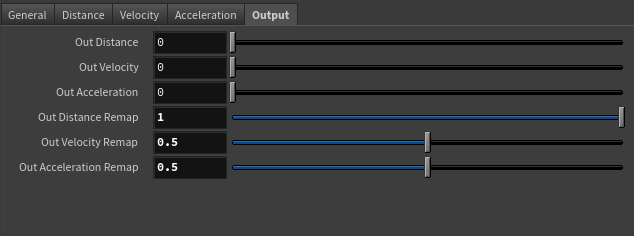
Out Velocity
Float
0.0
✗
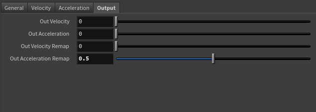
Magnitude of the velocity of the transform node. It is the raw value calculated before the remapping.
Out Acceleration
Float
0.0
✗
Magnitude of the acceleration of the transform node. It is the raw value calculated before the remapping.
Remapped Output
Name
Type
Default
Animatable
Description
Out Velocity Remap
Float
0.0
✗
Output remapped velocity. It is the result of remapping the Out Velocity. The detail attribute containing this activation information is adnActivationVelocity.
Out Acceleration Remap
Float
0.0
✗
Output remapped acceleration. It is the result of remapping the Out Acceleration. The detail attribute containing this activation information is adnActivationAcceleration.
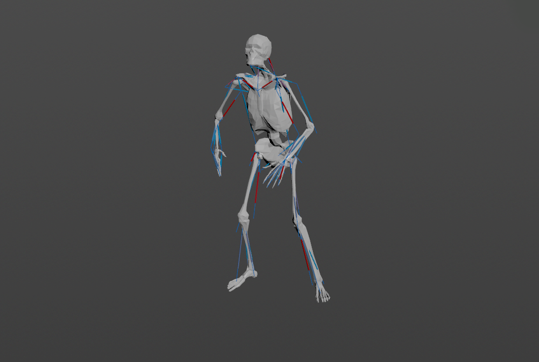
AdnSensorDistance is the sensor for computing meaningful output raw values representing the distance, velocity or acceleration between two transform nodes. Additionally, the sensor remaps the values of distance, velocity and acceleration to produce desirable activation values within a certain range to drive the simulation of an AdonisFX deformer. This sensor has to work in combination with an AdnLocatorDistance both for setup and visualization. An example use case for this sensor would be applying it to the connection made between bones which would compute the distance between two bones moving together.
An AdnSensorDistance will be in charge of computing, remapping and feeding activation (or other) values into the AdnLocatorDistance for visualization purposes, which in turn feeds the AdonisFX deformers to drive the simulation. The value of the sensor can be used, for example, to drive the activation of a muscle simulating contraction to increase its stiffness.
Figure 7: AdnSensorDistance used in a human model.
Two transforms will be required to create the AdnSensorDistance. To create an AdnSensorDistance and connect it to an existing AdnLocatorDistance:
Go to the geometry context of the rig containing the rig setup to which the sensors should be applied.
Press TAB and navigate to the submenu AdonisFX > Sensors to find the AdnSensorDistance SOP type.
Create it and connect the output of the AdnSensorDistance sensor to its corresponding AdnLocatorDistance input.
Go to the AdnSensorDistance's Input tab and select the transform nodes from which to extract the transformation from (e.g. joints, null nodes, rivets, etc). Use the "Operator Chooser" in the locator's UI to select the correct target node containing transform information. Generally these input nodes will be located on the /obj level as a null, joint or rivet.
The AdnSensorDistance is created and ready to be used with its corresponding AdnLocatorDistance.
Figure 8: AdnSensorDistance and AdnLocatorDistance in the node graph. The connection is created via detail expression to the AdnMuscle node.
NOTE
Activation values are output from the sensor nodes via detail attributes (adnActivationDistance, adnActivationVelocity and adnActivationAcceleration). It is to note that these attribute names are expected by the locator nodes and their name should not be altered.
When connecting the sensors to a muscle or an activation node for example it is advisable to first connect the sensor to its corresponding locator and use the locator node as reference for creating the detail expression connection.
To create a connection to the muscle use a detail expression on the muscle's parameter (for example the activation parameter) in the form of: detail("/obj/geo1/AdnLocatorDistance1", "adnActivationDistance", 0) pointing directly to the locator that is connected to the sensor. This will allow for the muscle nodes to pick up the detail activation attribute from the sensor connection.
Matrix containing the position in world space of the first transform node. This entry is an operator path pointing to nodes that contain transform information to drive the locator. These nodes are generally exposed on the /obj level.
End Matrix
Matrix
Identity
✓
Matrix containing the position in world space of the second transform node. This entry is an operator path pointing to nodes that contain transform information to drive the locator. These nodes are generally exposed on the /obj level.
Time Attributes
Name
Type
Default
Animatable
Description
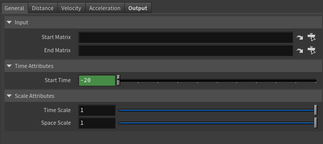
Start Time
Time
Current frame
✗
Determines the frame at which the playback/simulation starts.
Scale Attributes
Name
Type
Default
Animatable
Description
Time Scale
Float
1.0
✓
Sets the scaling factor applied to the compute the velocity or acceleration. Has a range of [0.001, 10.0]. The upper limit is soft, higher values can be used.
Space Scale
Float
1.0
✓
Sets the scaling factor applied to velocity or acceleration. Has a range of [0.001, 100.0]. The upper limit is soft, higher values can be used.
Distance Remap Settings
Name
Type
Default
Animatable
Description
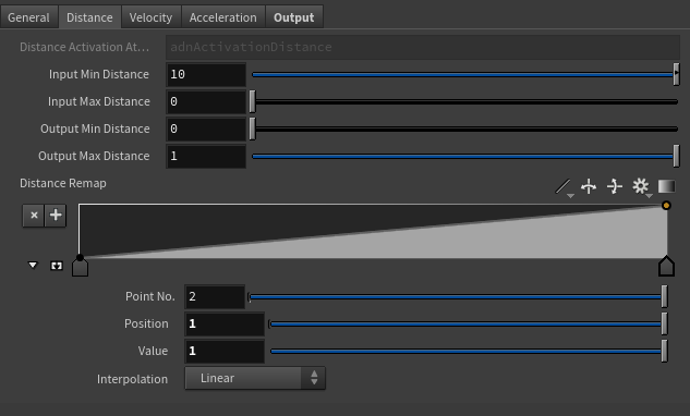
Distance Activation Attribute
float
0.0
✗
Specifies the name of the detail attribute that is used for exporting the remapped activation value. The expected attribute name is adnActivationDistance.
Input Min Distance
Float
0.0
✓
Lower limit of the range used to map the Distance value before evaluating it on the ramp attribute.
Input Max Distance
Float
0.0
✓
Upper limit of the range used to map the Distance value before evaluating it on the ramp attribute.
Output Min Distance
Float
0.0
✓
Lower limit of the range used to map the value returned by the ramp attribute and calculate the final remapped Distance.
Output Max Distance
Float
1.0
✓
Upper limit of the range used to map the value returned by the ramp attribute and calculate the final remapped Distance.
Selected Position
Float
0.0
✓
X-axis value of the ramp attribute.
Selected Value
Float
0.0
✓
Y-axis value of the ramp attribute.
Interpolation
Enumerator
Linear
✓
Interpolation method to be used between every two consecutive points in the ramp. There are seven options: Constant, Linear, Catmull-Rom, Monotone Cubic, Bezier, B-Spline, Hermite
Velocity Remap Settings
Name
Type
Default
Animatable
Description
Velocity Activation Attribute
float
0.0
✗
Specifies the name of the detail attribute that is used for exporting the remapped activation value. The expected attribute name is adnActivationVelocity.
Selected Position
Float
0.0
✓
X-axis value of the ramp attribute.
Selected Value
Float
0.0
✓
Y-axis value of the ramp attribute.
Interpolation
Enumerator
Linear
✓
Interpolation method to be used between every two consecutive points in the ramp. There are seven options: Constant, Linear, Catmull-Rom, Monotone Cubic, Bezier, B-Spline, Hermite
Input Min Velocity
Float
-10.0
✓
Lower limit of the range used to map the Out Velocity value before evaluating it on the ramp attribute.
Input Max Velocity
Float
10.0
✓
Upper limit of the range used to map the Out Velocity value before evaluating it on the ramp attribute.
Output Min Velocity
Float
0.0
✓
Lower limit of the range used to map the value returned by the ramp attribute and calculate the final remapped velocity.
Output Max Velocity
Float
1.0
✓
Upper limit of the range used to map the value returned by the ramp attribute and calculate the final remapped velocity.
Acceleration Remap Settings
Name
Type
Default
Animatable
Description
Acceleration Activation Attribute
float
0.0
✗
Specifies the name of the detail attribute that is used for exporting the remapped activation value. The expected attribute name is adnActivationAcceleration.
Input Min Acceleration
Float
-10.0
✓
Lower limit of the range used to map the Out Acceleration value before evaluating it on the ramp attribute.
Input Max Acceleration
Float
10.0
✓
Upper limit of the range used to map the Out Acceleration value before evaluating it on the ramp attribute.
Output Min Acceleration
Float
0.0
✓
Lower limit of the range used to map the value returned by the ramp attribute and calculate the final remapped acceleration.
Output Max Acceleration
Float
1.0
✓
Upper limit of the range used to map the value returned by the ramp attribute and calculate the final remapped acceleration.
Selected Position
Float
0.0
✓
X-axis value of the ramp attribute.
Selected Value
Float
0.0
✓
Y-axis value of the ramp attribute.
Interpolation
Enumerator
Linear
✓
Interpolation method to be used between every two consecutive points in the ramp. There are seven options: Constant, Linear, Catmull-Rom, Monotone Cubic, Bezier, B-Spline, Hermite
Output
Name
Type
Default
Animatable
Description
Out Distance
Float
0.0
✗
Magnitude of the distance between the transform nodes.
Out Velocity
Float
0.0
✗
Magnitude of the velocity between the transform nodes.
Out Acceleration
Float
0.0
✗
Magnitude of the acceleration between the transform nodes.
Remapped Output
Name
Type
Default
Animatable
Description
Out Distance Remap
Float
0.0
✗
Output remapped distance. It is the result of remapping the Out Distance. It is the raw value calculated before the remapping. The detail attribute containing this activation information is adnActivationDistance.
Out Velocity Remap
Float
0.0
✗
Output remapped velocity. It is the result of remapping the Out Velocity. It is the raw value calculated before the remapping. The detail attribute containing this activation information is adnActivationVelocity.
Out Acceleration Remap
Float
0.0
✗
Output remapped acceleration. It is the result of remapping the Out Acceleration. It is the raw value calculated before the remapping. The detail attribute containing this activation information is adnActivationAcceleration.
AdnSensorRotation is the sensor for computing meaningful output raw values representing the angle, angular velocity or angular acceleration between three transform nodes. Additionally, the sensor remaps the values of angle, velocity and acceleration to produce desirable activation values within a certain range to drive the simulation of an AdonisFX deformer. This sensor has to work in combination with an AdnLocatorRotation both for setup and visualization. An example use case for this sensor would be applying it to the arc connection made between bones which would compute the angle between two bones rotating.
An AdnSensorRotation will be in charge of computing, remapping and feeding activation (or other) values into the AdnLocatorRotation for visualization purposes, which in turn feeds the AdonisFX deformers to drive the simulation. The value of the sensor can be used, for example, to drive the activation of a muscle simulating contraction to increase its stiffness.
Figure 14: AdnSensorRotation used in a human model.
Three transforms will be required to create the AdnSensorRotation. To create an AdnSensorRotation and connect it to an existing AdnLocatorRotation:
Go to the geometry context of the rig containing the rig setup to which the sensors should be applied.
Press TAB and navigate to the submenu AdonisFX > Sensors to find the AdnSensorRotation SOP type.
Create it and connect the output of the AdnSensorRotation sensor to its corresponding AdnLocatorRotation input.
Go to the AdnSensorRotation's Input tab and select the transform nodes from which to extract the transformation from (e.g. joints, null nodes, rivets, etc). Use the "Operator Chooser" in the locator's UI to select the correct target node containing transform information. Generally these input nodes will be located on the /obj level as a null, joint or rivet.
The AdnSensorRotation is created and ready to be used with its corresponding AdnLocatorRotation.
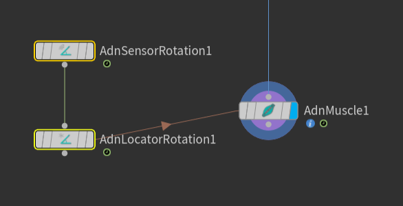
Figure 15: AdnSensorRotation and AdnLocatorRotation in the node graph. The connection is created via detail expression to the AdnMuscle node.
NOTE
Activation values are output from the sensor nodes via detail attributes (adnActivationRotation, adnActivationVelocity and adnActivationAcceleration). It is to note that these attribute names are expected by the locator nodes and their name should not be altered.
When connecting the sensors to a muscle or an activation node for example it is advisable to first connect the sensor to its corresponding locator and use the locator node as reference for creating the detail expression connection.
To create a connection to the muscle use a detail expression on the muscle's parameter (for example the activation parameter) in the form of: detail("/obj/geo1/AdnLocatorRotation1", "adnActivationRotation", 0) pointing directly to the locator that is connected to the sensor. This will allow for the muscle nodes to pick up the detail activation attribute from the sensor connection.
Matrix containing the position in world space of the first transform node. This entry is an operator path pointing to nodes that contain transform information to drive the locator. These nodes are generally exposed on the /obj level.
Mid Matrix
Matrix
Identity
✓
Matrix containing the position in world space of the second transform node. This entry is an operator path pointing to nodes that contain transform information to drive the locator. These nodes are generally exposed on the /obj level.
End Matrix
Matrix
Identity
✓
Matrix containing the position in world space of the third transform node. This entry is an operator path pointing to nodes that contain transform information to drive the locator. These nodes are generally exposed on the /obj level.
Time Attributes
Name
Type
Default
Animatable
Description
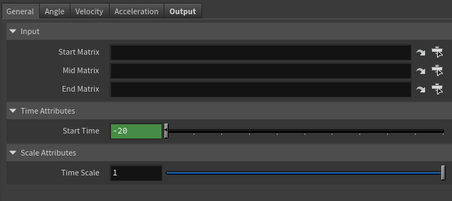
Start Time
Time
Current frame
✗
Determines the frame at which the playback/simulation starts.
Scale Attributes
Name
Type
Default
Animatable
Description
Time Scale
Float
1.0
✓
Sets the scaling factor applied to the compute the velocity or acceleration. Has a range of [0.001, 10.0]. The upper limit is soft, higher values can be used.
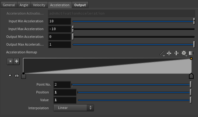
Angle Remap Settings
Name
Type
Default
Animatable
Description
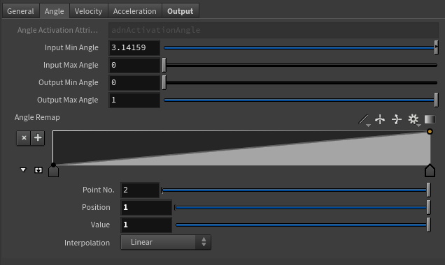
Angle Activation Attribute
float
0.0
✗
Specifies the name of the detail attribute that is used for exporting the remapped activation value. The expected attribute name is adnActivationAngle.
Selected Position
Float
0.0
✓
X-axis value of the ramp attribute.
Selected Value
Float
0.0
✓
Y-axis value of the ramp attribute.
Interpolation
Enumerator
Linear
✓
Interpolation method to be used between every two consecutive points in the ramp. There are seven options: Constant, Linear, Catmull-Rom, Monotone Cubic, Bezier, B-Spline, Hermite
Input Min Angle
Float
3.14
✓
Lower limit of the range used to map the Out Angle value before evaluating it on the ramp attribute.
Input Max Angle
Float
0.0
✓
Upper limit of the range used to map the Out Angle value before evaluating it on the ramp attribute.
Output Min Angle
Float
0.0
✓
Lower limit of the range used to map the value returned by the ramp attribute and calculate the final remapped angle.
Output Max Angle
Float
1.0
✓
Upper limit of the range used to map the value returned by the ramp attribute and calculate the final remapped angle.
Velocity Remap Settings
Name
Type
Default
Animatable
Description
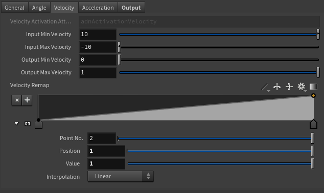
Velocity Activation Attribute
float
0.0
✗
Specifies the name of the detail attribute that is used for exporting the remapped activation value. The expected attribute name is adnActivationVelocity.
Selected Position
Float
0.0
✓
X-axis value of the ramp attribute.
Selected Value
Float
0.0
✓
Y-axis value of the ramp attribute.
Interpolation
Enumerator
Linear
✓
Interpolation method to be used between every two consecutive points in the ramp. There are seven options: Constant, Linear, Catmull-Rom, Monotone Cubic, Bezier, B-Spline, Hermite
Input Min Velocity
Float
10.0
✓
Lower limit of the range used to map the Out Velocity value before evaluating it on the ramp attribute.
Input Max Velocity
Float
-10.0
✓
Upper limit of the range used to map the Out Velocity value before evaluating it on the ramp attribute.
Output Min Velocity
Float
0.0
✓
Lower limit of the range used to map the value returned by the ramp attribute and calculate the final remapped velocity.
Output Max Velocity
Float
1.0
✓
Upper limit of the range used to map the value returned by the ramp attribute and calculate the final remapped velocity.
Acceleration Remap Settings
Name
Type
Default
Animatable
Description
Acceleration Activation Attribute
float
0.0
✗
Specifies the name of the detail attribute that is used for exporting the remapped activation value. The expected attribute name is adnActivationAcceleration.
Selected Position
Float
0.0
✓
X-axis value of the ramp attribute.
Selected Value
Float
0.0
✓
Y-axis value of the ramp attribute.
Interpolation
Enumerator
Linear
✓
Interpolation method to be used between every two consecutive points in the ramp. There are seven options: Constant, Linear, Catmull-Rom, Monotone Cubic, Bezier, B-Spline, Hermite
Input Min Acceleration
Float
10.0
✓
Lower limit of the range used to map the Out Acceleration value before evaluating it on the ramp attribute.
Input Max Acceleration
Float
-10.0
✓
Upper limit of the range used to map the Out Acceleration value before evaluating it on the ramp attribute.
Output Min Acceleration
Float
0.0
✓
Lower limit of the range used to map the value returned by the ramp attribute and calculate the final remapped acceleration.
Output Max Acceleration
Float
1.0
✓
Upper limit of the range used to map the value returned by the ramp attribute and calculate the final remapped acceleration.
Output
Name
Type
Default
Animatable
Description
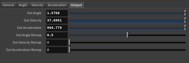
Out Angle
Float
0.0
✗
Magnitude of the angle between the three transform nodes. It is the raw value calculated before the remapping.
Out Velocity
Float
0.0
✗
Magnitude of the angular velocity between the three transform nodes. It is the raw value calculated before the remapping.
Out Acceleration
Float
0.0
✗
Magnitude of the angular acceleration between the three transform nodes. It is the raw value calculated before the remapping.
Remapped Output
Name
Type
Default
Animatable
Description
Out Angle Remap
Float
0.0
✗
Output remapped angle. It is the result of remapping the Out Angle. The detail attribute containing this activation information is adnActivationAngle.
Out Velocity Remap
Float
0.0
✗
Output remapped velocity. It is the result of remapping the Out Velocity. The detail attribute containing this activation information is adnActivationVelocity.
Out Acceleration Remap
Float
0.0
✗
Output remapped acceleration. It is the result of remapping the Out Acceleration. The detail attribute containing this activation information is adnActivationAcceleration.
Connections in AdonisFX for Houdini should be handled in two ways:
Detail expression: detail("/obj/geo1/L_adnLocatorRotation_armFlexionShape", "adnActivationRotation", 0) where the first component should contain an API compliant naming convention and the second the detail attribute name that some of the AdonisFX SOP nodes output. This should be used when the requirement is for the connected geometry to cook before retrieving the detail attribute. This could be used for example to drive a parameter of the node using the activation value output from a sensor/locator.
Channel expression: ch("../AdnMuscle1/envelope") where the first component should contain an API compliant naming convention and the second the referenced channel to the parameter name. This could be used to for example connect a float attribute to drive a parameter on the node.

 SOP type.
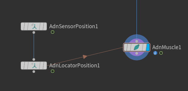
 SOP type.
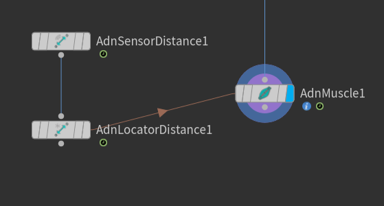
 SOP type.