
AdnRibbonMuscle
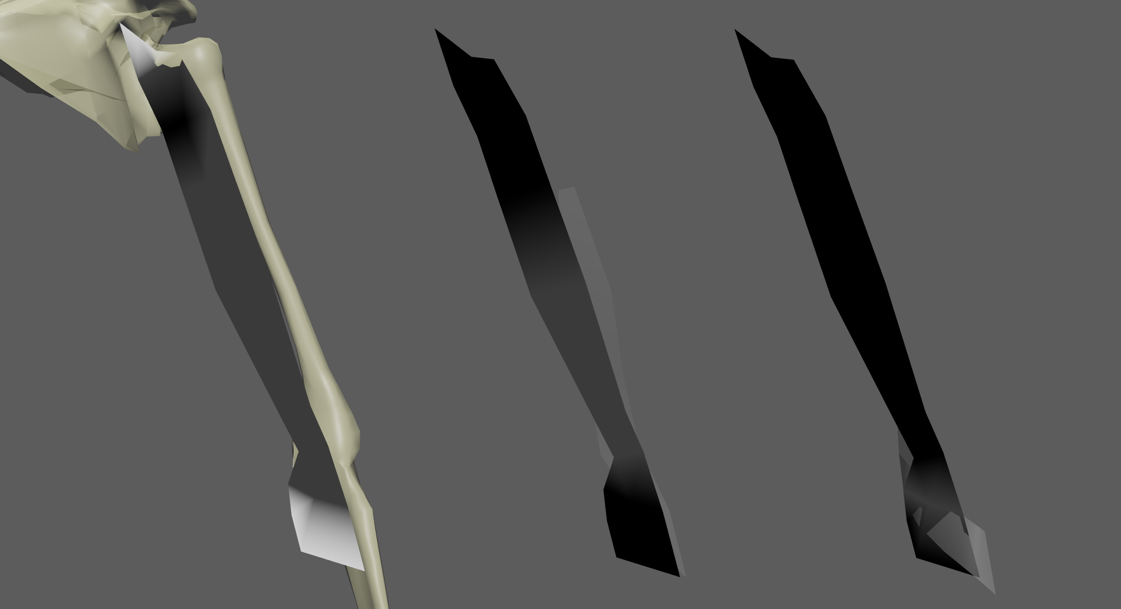
AdnRibbonMuscle is a Maya deformer for fast, robust and easy-to-configure muscle simulation on a surface. Thanks to the combination of internal (structural) and external (attachment and slide) constraints, this deformer can produce dynamics that allow the mesh to acquire the simulated characteristics of a ribbon with fibers activations to modulate the rigidity, and attachments to external objects to follow the global kinematics of the character.
The influence these constraints have on the simulated mesh can be freely modified by painting them via the AdonisFX Paint Tool or by uniformly regulating their influence via multipliers in the Attribute Editor. Besides the maps and multipliers there are many other parameters to regulate the muscle's dynamics and behavior to a wide array of options.
How To Use
The AdnRibbonMuscle deformer is of great simplicity to set up and apply to a mesh within a Maya scene. The way this deformer works is by applying simulation on top a mesh emulating a ribbon muscle which follows the dynamics of attachment points set as anchors. Those attachments mark the anchor points for the muscle, prepared to act as tendons, and will introduce a great part of the dynamics to the deformer.
To create an AdnRibbonMuscle deformer within a Maya scene, the following inputs must be provided:
- Targets (T): List of objects with which the simulated muscle will interact. The targets can be either transform nodes (e.g. rig joints, locators, etc) or geometries (e.g. bones or other muscles). Providing a list of targets is optional on create. However, they are required to add attachment and sliding behaviors to the muscle. One or multiple targets are supported.
- Muscle Geometry (M): Mesh that the AdnRibbonMuscle deformer will be applied to.
It is not mandatory to select the targets on creation of the AdnRibbonMuscle deformer. Targets can be added and removed after creating the deformer. For more information check the advanced section.
Follow these steps to create an AdnRibbonMuscle deformer:
- Select the Targets (if any) and the Muscle Geometry in that order.
- Press the
 button in the AdonisFX shelf or press Ribbon Muscle in the Solvers submenu from the AdonisFX menu. If the shelf button is double-clicked or the option box in the menu is selected a window will be displayed where a custom name and initial attribute values can be set.
 - AdnRibbonMuscle is ready to simulate with default settings. Check the next section to customize their configuration.
Attributes
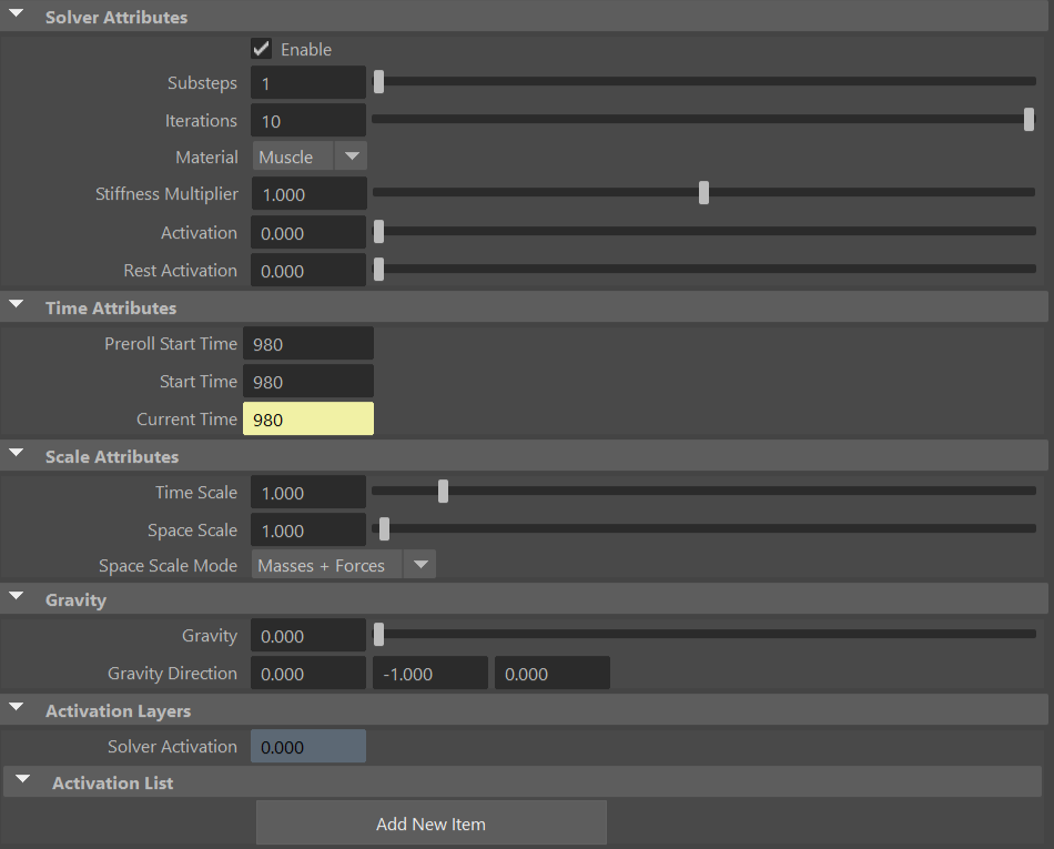
Solver Attributes
| Name | Type | Default | Animatable | Description |
|---|---|---|---|---|
| Enable | Boolean | True | ✓ | Flag to enable or disable the deformer computation. |
| Substeps | Integer | 1 | ✓ | Number of steps that the solver will execute per simulation frame. Greater values mean greater computational cost. Has a range of [1, 10]. The upper limit is soft, higher values can be used. |
| Iterations | Integer | 10 | ✓ | Number of iterations that the solver will execute per simulation step. Greater values mean greater computational cost. Has a range of [1, 10]. The upper limit is soft, higher values can be used. |
| Material | Enumerator | Muscle | ✓ | Solver stiffness presets per material. The materials are listed from lowest to highest stiffness. There are 8 different presets: Fat: 103, Muscle: 5e3, Rubber: 106, Tendon: 5e7, Leather: 108, Wood: 6e9, Skin: 12e3. |
| Stiffness Multiplier | Float | 1.0 | ✓ | Multiplier factor to scale up or down the material stiffness. Has a range of [0.0, 2.0]. The upper limit is soft, higher values can be used. |
| Activation | Float | 0.0 | ✓ | Current activation of the deformed ribbon muscle. The activation modifies the stiffness of the muscle depending on the fibers direction of the muscle. Has a range of [0.0, 1.0]. To ingest activations driven by multiple sensors into the muscle, refer to the AdnActivation page. |
| Rest Activation | Float | 0.0 | ✓ | Value representing the amount of rest activation to apply to the muscle. Has a range of [0.0, 1.0]. |
Time Attributes
| Name | Type | Default | Animatable | Description |
|---|---|---|---|---|
| Preroll Start Time | Time | Current frame | ✗ | Sets the frame at which the preroll begins. The preroll ends at Start Time. |
| Start Time | Time | Current frame | ✗ | Determines the frame at which the simulation starts. |
| Current Time | Time | Current frame | ✓ | Current playback frame. |
Scale Attributes
| Name | Type | Default | Animatable | Description |
|---|---|---|---|---|
| Time Scale | Float | 1.0 | ✓ | Sets the scaling factor applied to the simulation time step. Has a range of [0.0, 2.0]. The upper limit is soft, higher values can be used. |
| Space Scale | Float | 1.0 | ✓ | Sets the scaling factor applied to the masses and/or the forces (e.g. gravity). AdonisFX interprets the scene units in centimeters. If modeling your creature you apply a scaling factor for whatever reason (e.g. to avoid precision issues in Maya), you will have to adjust for this scaling factor using this attribute. If your character is supposed to be 170 units tall, but you prefer to model it to be 17 units tall, then you will need to set the space scale to a value of 10. This will ensure that your 17 units creature will simulate as if it was 170 units tall. Has a range of [0.0, 2.0]. The upper limit is soft, higher values can be used. |
| Space Scale Mode | Enumerator | Masses + Forces | ✓ | Determines if the spatial scaling affects the masses, the forces, or both. The available options are:
|
Gravity
| Name | Type | Default | Animatable | Description |
|---|---|---|---|---|
| Gravity | Float | 0.0 | ✓ | Sets the magnitude of the gravity acceleration in m/s2. The value is internally converted to cm/s2. Has a range of [0.0, 100.0]. The upper limit is soft, higher values can be used. |
| Gravity Direction | Float3 | {0.0, -1.0, 0.0} | ✓ | Sets the direction of the gravity acceleration. Vectors introduced do not need to be normalized, but they will get normalized internally. |
Activation Layers
| Name | Type | Default | Animatable | Description |
|---|---|---|---|---|
| Solver Activation | Float | 0.0 | ✗ | Shows the global activation value currently used by the solver. This global activation is the result of applying all the activation layers configured in the activation and activation list attributes. |
| Activation List | List | Empty | ✗ | List of activation layers where each item is a compound attribute of three elements: bypass operator, value and operator. |
| Activation List Bypass Operator | Boolean | True | ✓ | If enabled, it bypasses the current operator in the activation list, which will not contribute to the final activation value. |
| Activation List Value | Float | 0.0 | ✓ | Activation value that will contribute, given the operator type, to the final activation. |
| Activation List Operator | Enumerator | Add | ✓ | Operator used to contribute to the final activation. This can be: Over, Add, Sub, Mult, Divide. |
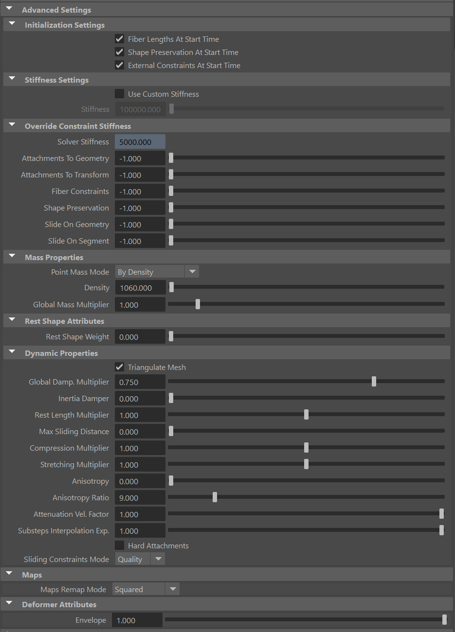
Advanced Settings
Initialization Settings
| Name | Type | Default | Animatable | Description |
|---|---|---|---|---|
| Fiber Lengths At Start Time | Boolean | True | ✗ | Flag that forces the fiber constraints to reinitialize the rest length at start time. This attribute has effect only if preroll start time is lower than start time. |
| Shape Preservation At Start Time | Boolean | False | ✗ | Flag that forces the shape preservation constraints to reinitialize at start time. This attribute has effect only if preroll start time is lower than start time. |
| External Constraints At Start Time | Boolean | True | ✗ | Flag that forces the external constraints (attachments to transform, attachments to geometry, slide on segment and slide on geometry) to reinitialize at start time. This attribute has effect only if preroll start time is lower than start time. |
Stiffness Settings
| Name | Type | Default | Animatable | Description |
|---|---|---|---|---|
| Use Custom Stiffness | Boolean | False | ✓ | Toggles the use of a custom stiffness value. If custom stiffness is used, Material and Stiffness Multiplier will be disabled and Stiffness will be used instead. |
| Stiffness | Float | 105 | ✓ | Sets the custom stiffness value. Its value must be greater than 0.0. |
Override Constraint Stiffness
| Name | Type | Default | Animatable | Description |
|---|---|---|---|---|
| Solver Stiffness | Float | 0.0 | ✗ | Shows the global stiffness value currently used by the solver. |
| Attachments To Geometry | Float | -1.0 | ✓ | Sets the stiffness override value for attachment to geometry constraints. If the value is less than 0.0, the global stiffness will be used. Otherwise, this custom stiffness will override the global stiffness. Has a range of [0.0, 1012]. The upper limit is soft, higher values can be used. |
| Attachments To Transform | Float | -1.0 | ✓ | Sets the stiffness override value for attachment to transform constraints. If the value is less than 0.0, the global stiffness will be used. Otherwise, this custom stiffness will override the global stiffness. Has a range of [0.0, 1012]. The upper limit is soft, higher values can be used. |
| Fiber Constraints | Float | -1.0 | ✓ | Sets the stiffness override value for fiber constraints. If the value is less than 0.0, the global stiffness will be used. Otherwise, this custom stiffness will override the global stiffness. Has a range of [0.0, 1012]. The upper limit is soft, higher values can be used. |
| Shape Preservation | Float | -1.0 | ✓ | Sets the stiffness override value for shape preservation constraints. If the value is less than 0.0, the global stiffness will be used. Otherwise, this custom stiffness will override the global stiffness. Has a range of [0.0, 1012]. The upper limit is soft, higher values can be used. |
| Slide On Geometry | Float | -1.0 | ✓ | Sets the stiffness override value for slide on geometry constraints. If the value is less than 0.0, the global stiffness will be used. Otherwise, this custom stiffness will override the global stiffness. Has a range of [0.0, 1012]. The upper limit is soft, higher values can be used. |
| Slide On Segment | Float | -1.0 | ✓ | Sets the stiffness override value for slide on segment constraints. If the value is less than 0.0, the global stiffness will be used. Otherwise, this custom stiffness will override the global stiffness. Has a range of [0.0, 1012]. The upper limit is soft, higher values can be used. |
Providing a stiffness override value of 0.0 will disable the computation of that constraint.
Mass Properties
| Name | Type | Default | Animatable | Description |
|---|---|---|---|---|
| Point Mass Mode | Enumerator | By Density | ✓ | Defines how masses should be used in the solver.
|
| Density | Float | 1060.0 | ✓ | Sets the density value in kg/m3 to be able to estimate mass values with By Density mode. The value is internally converted to g/cm3. Has a range of [0.001, 106]. Lower and upper limits are soft, lower and higher values can be used. |
| Global Mass Multiplier | Float | 1.0 | ✓ | Sets the scaling factor applied to the mass of every point. Has a range of [0.001, 10.0]. Lower and upper limits are soft, lower and higher values can be used. |
Rest Shapes Attributes
| Name | Type | Default | Animatable | Description |
|---|---|---|---|---|
| Rest Shape Weight | Float | 0.0 | ✓ | Defines the influence of the given rest shape to the final shape of the muscle. Has a range of [0.0, 1.0]. A value of 0.0 makes the solver ignore the rest shape. A value of 1.0 makes the solver refresh the data of fibers and shape preservation at each frame to align with the rest shape. A value between 0.0 and 1.0 applies an interpolation between the original constraints data (0.0) and the rest shape constraints data (1.0). Note that this parameter is ignored if there is no rest shape connected to the solver. |
Dynamic Properties
| Name | Type | Default | Animatable | Description |
|---|---|---|---|---|
| Triangulate Mesh | Boolean | True | ✗ | Use the internally triangulated mesh to build constraints. |
| Global Damping Multiplier | Float | 0.75 | ✓ | Sets the scaling factor applied to the global damping of every point. Has a range of [0.0, 1.0]. The upper limit is soft, higher values can be used. |
| Inertia Damper | Float | 0.0 | ✓ | Sets the linear damping applied to the dynamics of every point. Has a range of [0.0, 1.0]. The upper limit is soft, higher values can be used. |
| Rest Length Multiplier | Float | 1.0 | ✓ | Sets the scaling factor applied to the edge lengths at rest. Has a range of [0.0, 2.0]. The upper limit is soft, higher values can be used. |
| Max Sliding Distance | Float | 0.0 | ✗ | Determines the size of the sliding area. It corresponds to the maximum distance to the closest point on the target mesh computed on initialization. The higher this value is, the higher quality and the lower performance. If the value provided is considered too high for a given target mesh, a warning will be displayed to the user. Has a range of [0.0, 10.0]. The upper limit is soft, higher values can be used. |
| Compression Multiplier | Float | 1.0 | ✓ | Sets the scaling factor applied to the compression resistance of every point. Has a range of [0.0, 2.0]. The upper limit is soft, higher values can be used. |
| Stretching Multiplier | Float | 1.0 | ✓ | Sets the scaling factor applied to the stretching resistance of every point. Has a range of [0.0, 2.0]. The upper limit is soft, higher values can be used. |
| Anisotropy | Float | 0.0 | ✓ | Sets the anisotropic behavior of the fibers: 0 fully isotropic material, 1 fully anisotropic material. Has a range of [0.0, 1.0]. |
| Anisotropy Ratio | Float | 9.0 | ✓ | Sets the ratio of anisotropy of the muscle fibers to lower the stiffness on edges not aligned with the fibers flow: the higher this value is, the lower the stiffness of the orthogonal edges when the muscle is anisotropic. Has a range of [1.0, 50.0]. The upper limit is soft, higher values can be used. |
| Attenuation Velocity Factor | Float | 1.0 | ✓ | Sets the weight of the attenuation applied to the velocities of the simulated vertices driven by the Attenuation Matrix. Has a range of [0.0, 1.0]. The upper limit is soft, higher values can be used. |
| Substeps Interp. Exp. | Float | 1.0 | ✓ | Sets the exponential factor to weight the interpolation at each substep. Has a range of [0.0, 1.0]. The upper limit is soft, higher values can be used. A value of 0.0 disables the interpolation: input geometry targets and attenuation matrix are not interpolated. A value of 1.0 applies linear interpolation (input geometry targets and attenuation matrix) between previous and current frame based on a linear weight, i.e. weight = substep / num_substeps. A value between 0.0 and 1.0 applies exponential interpolation (input geometry targets and attenuation matrix) between previous and current frame based on an exponential weight, i.e. weight = (substep / num_substeps) ^ exponent. |
| Hard Attachments | Boolean | False | ✓ | If enabled, attachment constraints will force the vertices to stick to the target transformation completely. |
| Sliding Constraints Mode | Enumerator | Quality | ✓ | Defines the mode of execution for the slide on geometry constraints.
|
Maps
| Name | Type | Default | Animatable | Description |
|---|---|---|---|---|
| Maps Remap Mode | Enumerator | Squared | ✗ | Defines the mode of remapping the painted values of attachments to geometry, slide on geometry, attachments to transform, slide on segment and shape preservation constraints. The other paintable maps remain unmodified. Each remap mode applies a function to the input painted values (x) to get the final value used for the simulation (y).
|
Deformer Attributes
| Name | Type | Default | Animatable | Description |
|---|---|---|---|---|
| Envelope | Float | 1.0 | ✓ | Specifies the deformation scale factor. Has a range of [0.0, 1.0]. The upper and lower limits are soft, values can be set in a range of [-2.0, 2.0] |
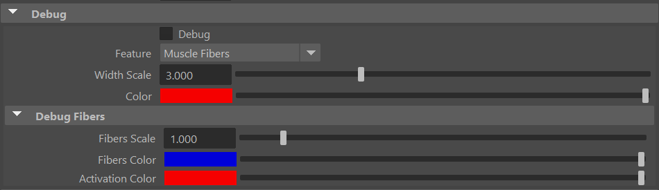
Debug Attributes
| Name | Type | Default | Animatable | Description |
|---|---|---|---|---|
| Debug | Boolean | False | ✓ | Enable or Disable the debug functionalities in the viewport for the AdnRibbonMuscle deformer. |
| Feature | Enumerator | Muscle Fibers | ✓ | A list of debuggable features for this deformer.
|
| Width Scale | Float | 3.0 | ✓ | Modifies the width of all lines. |
| Color | Color Picker | Red | ✓ | Selects the line color from a color wheel. Its saturation can be modified using the slider. |
| Fibers Scale | Float | 1.0 | ✓ | The scale can be modified to set a custom fiber length. |
| Fibers Color | Color Picker | Blue | ✓ | The fibers color when Muscle Fibers debug mode is selected and the muscle is not activated (Activation Attribute). |
| Activation Color | Color Picker | Red | ✓ | The fibers color when Muscle Fibers debug mode is selected and the muscle is activated (Activation Attribute). |
Connectable Attributes
| Name | Type | Default | Animatable | Description |
|---|---|---|---|---|
| Attenuation Matrix | Matrix | Identity | ✓ | Transformation matrix to drive the attenuation. |
| Attachment Matrix | Matrix | Identity | ✓ | List of transform attachment matrices (from a compound attribute) used for setting up transform attachments. |
| Slide On Segment Root Matrix | Matrix | Identity | ✓ | List of root matrices (from a compound attribute) used for setting up segments of slide on segment constraints. |
| Slide On Segment Tip Matrix | Matrix | Identity | ✓ | List of tip matrices (from a compound attribute) used for setting up segments of slide on segment constraints. |
| Target World Mesh | Mesh | ✓ | List of geometry meshes (from a compound attribute) used for setting up attachment to geometry and slide on geometry constraints. | |
| Target World Matrix | Matrix | Identity | ✓ | List of geometry matrices (from a compound attribute) used for setting up attachment to geometry and slide on geometry constraints. |
| Rest Shape Mesh | Mesh | ✓ | Geometry to drive the goal shape of the muscle during simulation. This geometry is used to refresh the data of the fibers, shape preservation and volume constraints at each frame. |
Attribute Editor Template
Paintable Weights
In order to provide more artistic control, some key parameters of the AdnRibbonMuscle solver are exposed as paintable attributes in the deformer. The AdonisFX Paint Tool must be used to paint those parameters to ensure that the values satisfy the solver requirements.
| Name | Default | Description |
|---|---|---|
| Attachments To Geometry | 0.0 | Multi-influence weight to indicate the influence of each geometry attachment at each vertex of the muscle. |
| Attachments To Transform | 0.0 | Multi-influence weight to indicate the influence of each transform attachment at each vertex of the muscle. |
| Compression Resistance | 1.0 | Force to correct the edge lengths if the current length is smaller than the rest length. A higher value represents higher correction. |
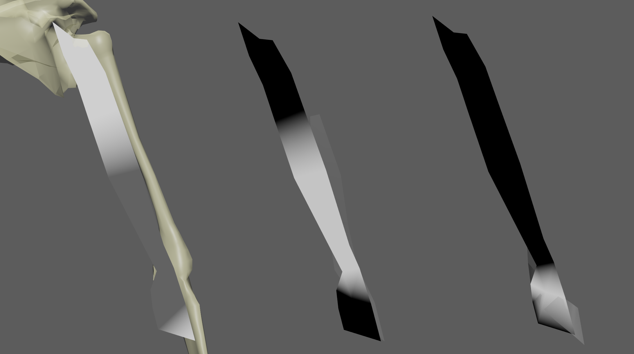
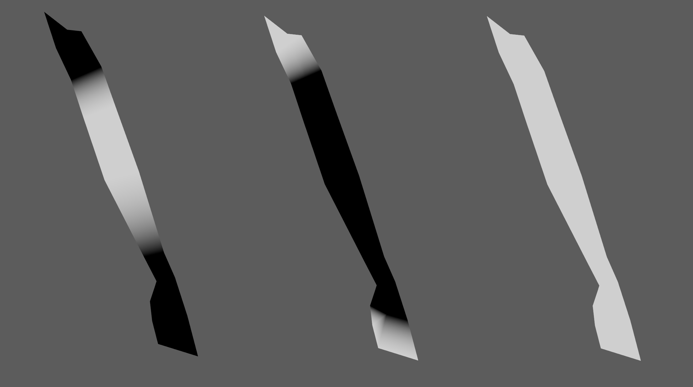
| Fibers | {0.0, 0.0, 0.0} | The deformer estimates the fiber directions at each vertex based on the tendon weights. In case that the estimated fibers do not fit well to the desired directions, the paint tool can be used to comb the fibers manually. The fibers can be displayed using the Muscle Fibers option in the debugger. |
| Fibers Multiplier | 1.0 | Controls the area in which to concentrate the activation of the muscle. A higher value means more concentrated activation. |
| Global Damping | 1.0 | Set global damping per vertex in the simulated mesh. The greater the value per vertex is the more it will attempt to retain its previous position. |
| Masses | 1.0 | Set individual mass values per vertex in the simulated mesh. |
| Shape Preservation | 1.0 | Amount of correction to apply to the current vertex to maintain the initial state of the shape formed with the surrounding vertices. |
| Slide On Geometry | 0.0 | Multi-influence weight to force vertices to displace only on the target geometry area defined by the Max Sliding Distance value. |
| Slide On Segment | 0.0 | Multi-influence weight to force vertices to displace only in the direction of a user-specified group of segments. |
| Sliding Distance Multiplier | 1.0 | Determines the size of the sliding area per vertex. It corresponds to the maximum distance to the closest point on the target mesh computed on initialization. Greater values will allow for larger sliding areas but will also increase the computational cost.
|
| Stretching Resistance | 1.0 | Force to correct the edge lengths if the current length is greater than the rest length. A higher value represents higher correction. |
| Tendons | 0.0 | Floating values to indicate the source of the muscle fibers. The solver will use that information to make an estimation of the fiber direction at each vertex. It is recommended to set a value of 1.0 wherever the tendinous tissue would be in an anatomically realistic muscle and a value of 0.0 in the rest of the mesh. |
- The attachment weights are normalized at each vertex. This normalization is applied when a stroke is finished. The use of the AdonisFX Paint Tool is mandatory for that.
- It is recommended to paint the values for the most influent attractors at the end in order to avoid the internal normalization overriding them in further strokes.
- Fibers and Tendon weights should only be painted on the initialization frame, being the initialization frame the lowest value between Preroll Start Time and Start Time.
Debugger
In order to better visualize deformer constraints and attributes in the Maya viewport there is the option to enable the debugger, found in the dropdown menu labeled Debug in the Attribute Editor.
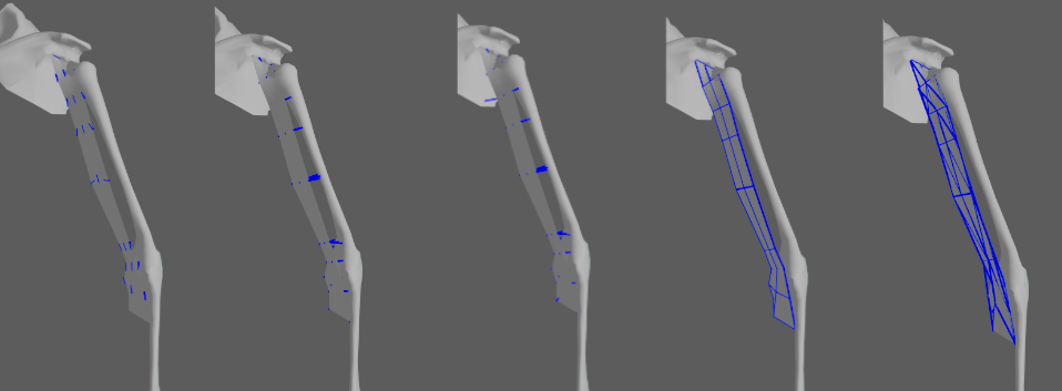
To enable the debugger the Debug checkbox must be marked. To select the specific feature to visualize, choose it from the list provided in Features. The features that can be visualized with the debugger in the AdnRibbonMuscle deformer are:
- Attachments To Geometry: For each vertex with a geometry attachment constraint weight greater than 0.0, a line will be drawn from the mesh vertex to its respective geometry target closest point at rest.
- Attachments To Transform: For each vertex with a transform attachment constraint weight greater than 0.0, a line will be drawn from the mesh vertex to its respective transform target.
- Fiber Constraints: For each pair of vertices forming a constraint a line will be drawn. If the Triangulate Mesh option is disabled the debugged lines will align with the edges of the mesh polygons. If the Triangulate Mesh option is enabled the debugged lines will align with the edges of the underlying triangulation of the mesh.
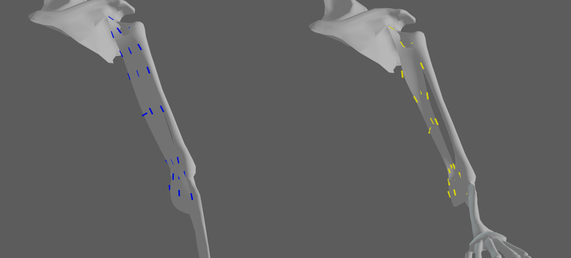
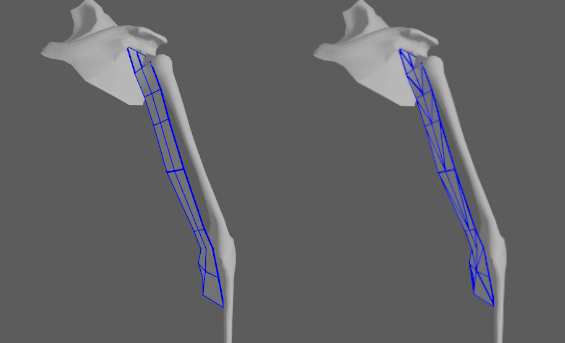
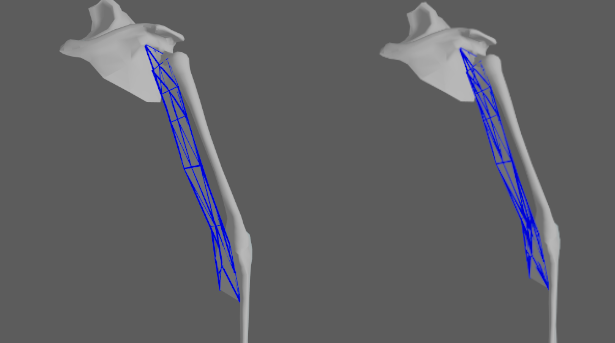
- Muscle Fibers: For each vertex, a line will be drawn showing the direction of the muscle fibers. In addition, the colors of the fibers will be modulated given the Activation value by interpolating the Fibers Color and the Activation Color. This will allow debugging the activation of the muscle more precisely.
- Shape Preservation: For each vertex with a shape preservation weight greater than 0.0, a line will be drawn from each adjacent vertex to the opposite adjacent vertex.
- Slide On Geometry: If the Max Sliding Distance value is greater than 0.0, for each vertex with a slide on geometry weight greater than 0.0, a line will be drawn from the mesh vertex to the closest point on its respective geometry target.
- Slide On Segment: For each vertex with a slide on segment weight greater than 0.0, a line will be drawn from the mesh vertex to the closest point to its respective segment.
Enabling the debugger and selecting one of these constraints will draw lines from the influenced vertices in the simulated mesh to their corresponding reference vertices.
Advanced
Targets
Once the AdnRibbonMuscle deformer is created, it is possible to add and remove new targets to the system. Targets that are transform based like joints and locators will be treated as transform targets. Targets that are mesh based will be considered as geometry targets.
- Add targets:
- Select the transform or mesh nodes (one or more) to be assigned as targets to the AdnRibbonMuscle.
- Select the mesh that has the AdnRibbonMuscle deformer applied.
- Press the
 button in the AdonisFX shelf or press Add Targets in the AdonisFX menu from the Edit Muscle submenu.
- Remove targets:
- Select one or more transform or mesh nodes that are assigned as targets to the AdnRibbonMuscle.
- Select the mesh that has the AdnRibbonMuscle deformer applied.
- Press the
 button in the AdonisFX shelf or press Remove Targets in the AdonisFX menu from the Edit Muscle submenu.
 - Alternatively, if only the mesh with the AdnRibbonMuscle deformer is selected, when pressing the button, all targets will get removed (transform and mesh targets).
Targets can be any transformation nodes or meshes. On one hand, transformation nodes such as joints or locators are used to create attachments to their world transformation matrices. On the other hand, meshes are used to create attachments to geometry and slide on geometry constraints. Check A Simple Setup for more information on how to paint the influence maps for the mentioned constraints.
- Attachments to geometry and slide on geometry constraints are meant to simulate muscle-to-bone and muscle-to-muscle interactions.
- For muscle-to-muscle interactions, only unidirectional relationships are supported. This means that having muscles A and B, it is possible to assign A as target of B or B as target of A, but not the two at the same time.
Slide On Segment Constraint
Additionally to all previously mentioned constraints, ribbon muscles can have an additional, optional constraint that can define a segment over which the muscle will slide.
- Add Segment:
- Select the transform nodes from which a segment would be created for the muscle to slide on.
- Select the mesh that has the AdnRibbonMuscle deformer applied.
- Press Add Slide On Segment Constraint in the AdonisFX menu from the Edit Muscle submenu.
- The transform node selection must follow a parent to child relationship in the hierarchy (like rig joints do).
- It is also recommended to paint only the vertices that are not attached to the rig, i.e. excluding the tendon vertices.
- This constraint is recommended especially for muscles on the limbs.
- Remove Segment:
- Select one or more transform nodes that are assigned as segment anchors to the AdnRibbonMuscle.
- Select the mesh that has the AdnRibbonMuscle deformer applied.
- Press Remove Slide On Segment Constraint in the AdonisFX menu from the Edit Muscle submenu.
- Alternatively, if only the mesh with the AdnRibbonMuscle deformer is selected, when pressing Remove Slide On Segment Constraint in the AdonisFX menu, all segments will be removed.
Rest Shape
The muscle solver supports an art-directed shape to drive the fibers, shape and volume constraints. This shape is typically a sculpted version of the muscle (it must be topologically identical) that represents the muscle when it is fully activated. The artist can add and remove the custom shape from dedicated entries in the AdonisFX muscle submenu.
- Add Rest Shape:
- Select the transform or mesh node to be assigned as rest shape to the AdnRibbonMuscle.
- Select the mesh that has the AdnRibbonMuscle deformer applied.
- Press Add Rest Shape in the AdonisFX menu from the Edit Muscle submenu.
- The topology of the rest shape and the muscle geometry must be identical (i.e. vertex count, vertex connectivity, polygonal information, etc.).
- Remove Rest Shape:
- Select the transform node of the rest mesh assigned to the AdnRibbonMuscle (optional).
- Select the mesh that has the AdnRibbonMuscle deformer applied.
- Press Remove Rest Shape in the AdonisFX menu from the Edit Muscle submenu.
On top of this, if the input activation of the muscle is also connected to the Rest Shape Weight, then the influence of the rest shape over the final result will be coherent with the variation of the level of activation during the simulation.
Fibers Multiplier
Painting the fibers multiplier map allows to concentrate the activation of a muscle in certain areas which would allow for more artistic control over the final shape of the muscle after contraction (activation). Not painting the fibers multiplier map will cause the muscle to contract uniformly over its whole surface without concentrating the activations in the belly of the muscle. Painting to 0.0 the tendinous areas and painting to 1.0 the belly of the muscle will allow (after combing fibers and activating the muscle) to activate only the areas that had been painted with a value of 1.0.
Activation Layers
The activation layers allow to drive the muscle activation by multiple sensors combined together without the need of using an AdnActivation node. In practice, having an AdnActivation node with multiple input sensors connected to the activation attribute of an AdnRibbonMuscle is equivalent to connecting those sensors directly to the activation list of that muscle.
The activation layers contribute to the final activation of the muscle solver, where the first layer will always be the activation scalar attribute. Then, every value in the activation list array plug is applied on top taking into consideration the operator and the bypass flag. The resulting value is the global activation that the solver will use for the simulation, and it is written onto the read-only output solver activation attribute.
The operators available are:
- Over (Override): Overrides the accumulated solver activation value with Value. If the current accumulated activation value is 1.0 and Value is 2.0 then the new accumulated value will be 2.0.
- Add (Add): Adds the accumulated solver activation value with Value. If the current accumulated activation value is 1.0 and Value is 2.0 then the new accumulated value will be 3.0.
- Sub (Subtract): Subtracts the accumulated solver activation value with Value. If the current accumulated activation value is 1.0 and Value is 2.0 then the new accumulated value will be -1.0.
- Mult (Multiply): Multiplies the accumulated solver activation value with Value. If the current accumulated activation value is 1.0 and Value is 2.0 then the new accumulated value will be 2.0.
- Div (Divide): Divides the accumulated solver activation value with Value. If the current accumulated activation value is 1.0 and Value is 2.0 then the new accumulated value will be 0.5.
- All operators will be evaluated from top to bottom (starting from the lowest index and ending on the last index used).
- The final value will be clamped in the range 0 to 1 to ensure that the solver activation is always normalized.
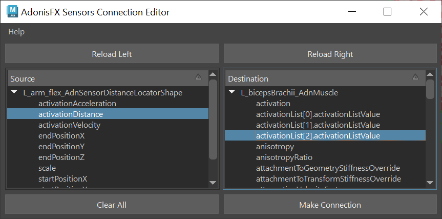
The sensors can be connected to the activation list using the Sensors Connection Editor tool. By selecting the geometry with a muscle applied and loading it in the list on the right side of the UI, the plug values of each activation layer will be listed to overwrite the connection, plus the next available index in the array plug.
The removal of input sensors connected to the activation list can be done from the AdonisFX menu in Activation > Remove Inputs option.

