
A Simple Setup
This page is dedicated to explain, step by step, a simple process of creating and setting the main AdonisFX solvers and deformers SOPs in Houdini. The scenarios presented here are intended to provide the minimum required configurations to obtain plausible results.
AdnMuscle
To create a basic scenario using the AdnMuscle SOP deformer, start with a scene with the following elements:
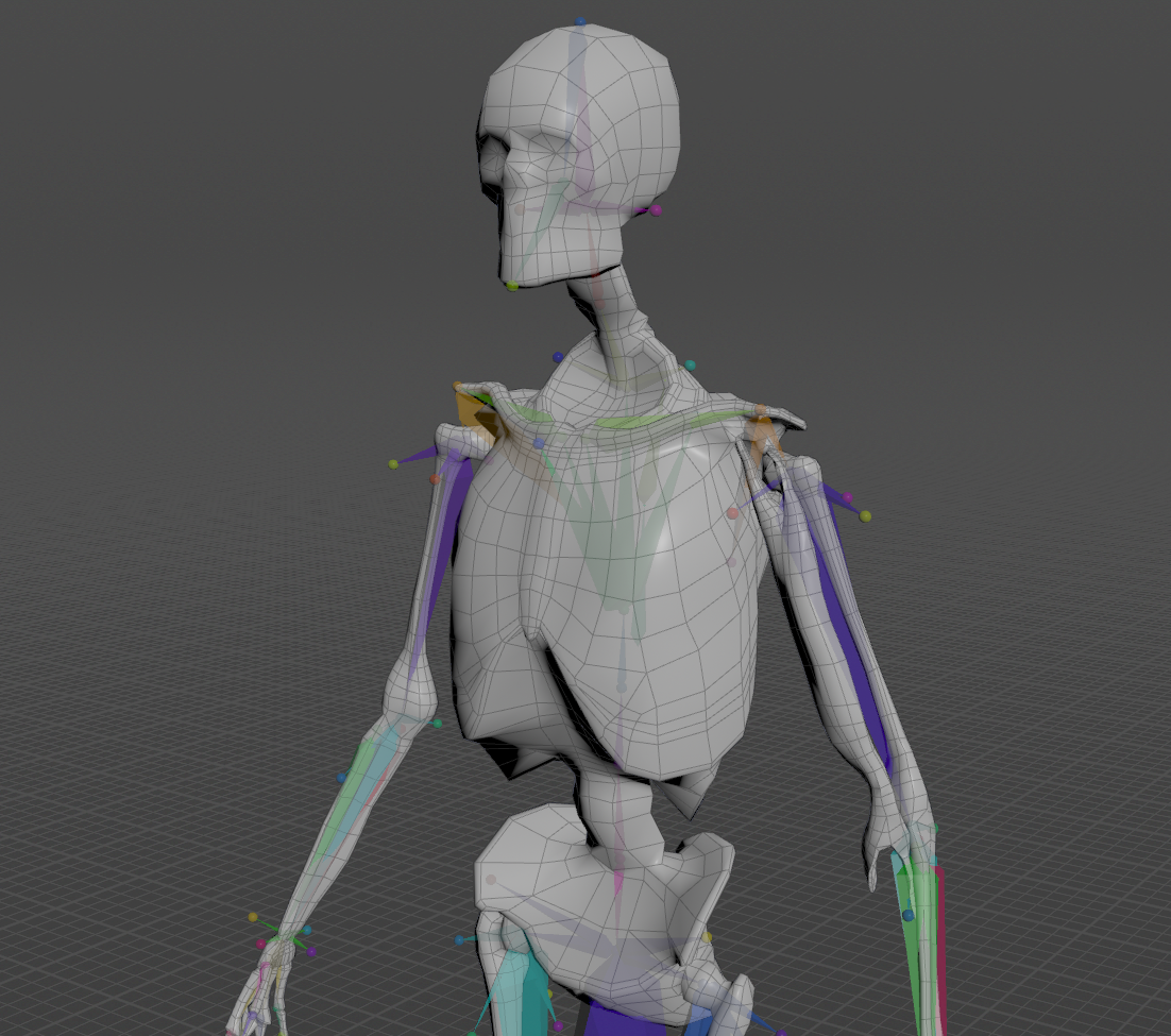
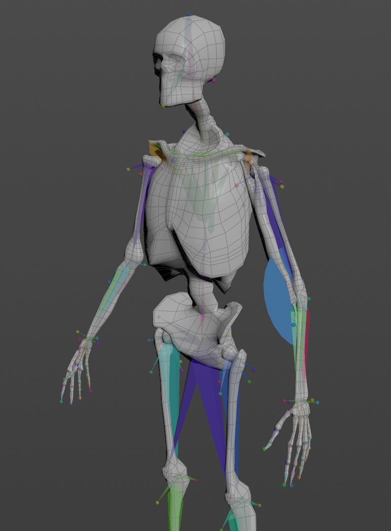
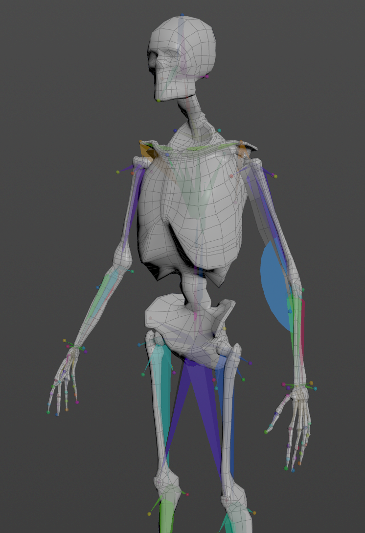
- An animation rig or a skeletal mesh (i.e. the mummy) or both.
- A geometry representing the muscle to simulate.
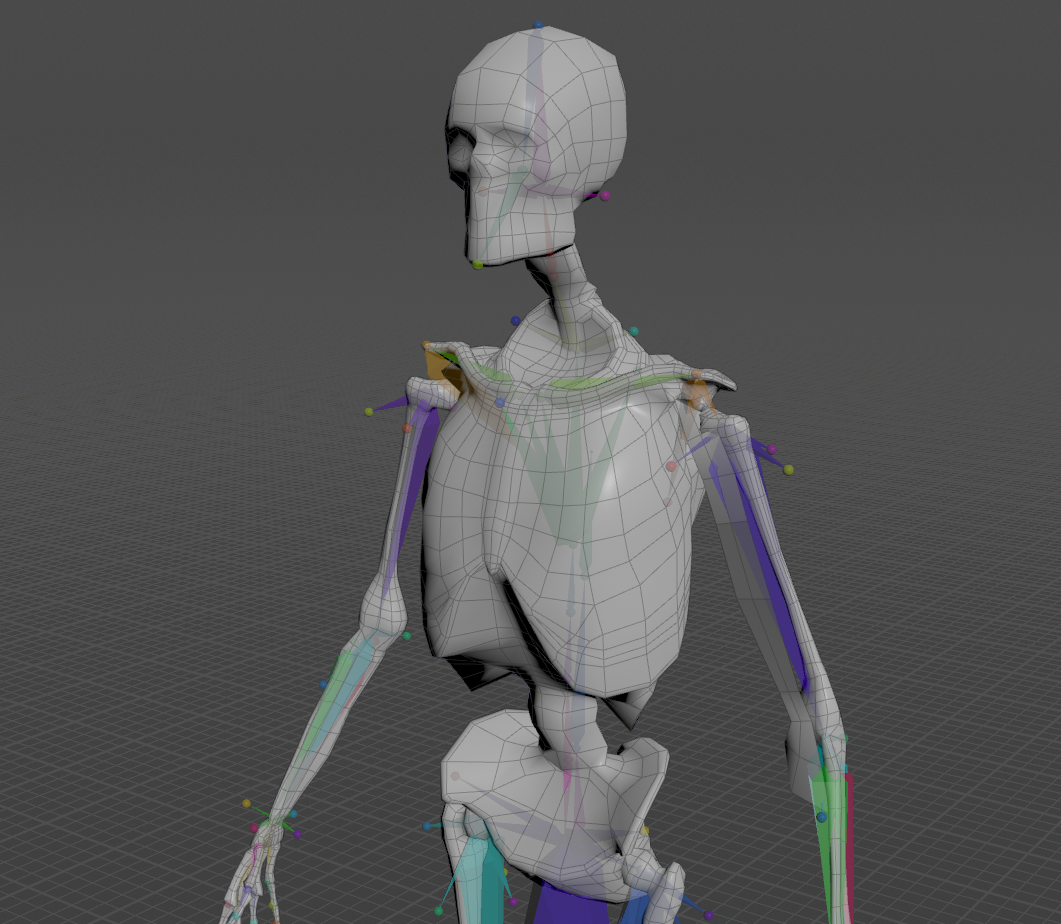
In this case the proposed example is to simulate a biceps in an animated full body rig. The AdnMuscle SOP will be applied to the mesh of the biceps.
Create Deformer
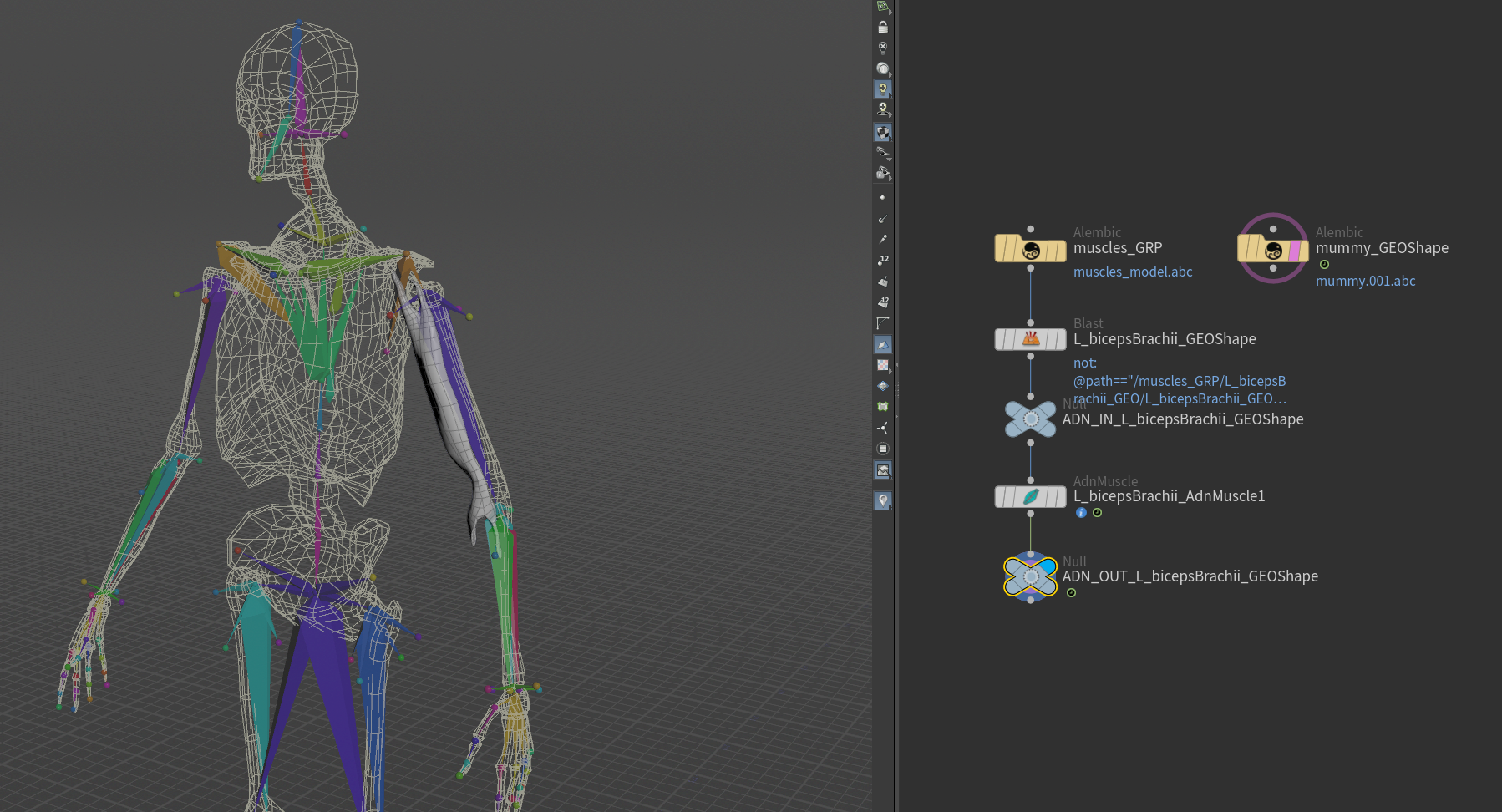
To create the AdnMuscle SOP, press TAB and navigate to the submenu AdonisFX > Solvers to find the AdnMuscle SOP  type. Then connect the muscle geometry to the input of the AdnMuscle node.
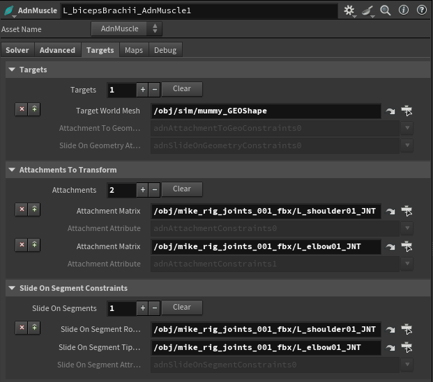
In order to add targets to the muscles, go to the Targets tab on the AdnMuscle node, press + under the Targets collapsible to add a new entry and provide the path to the SOP containing the target geometry. The geometries added as targets can be used to drive attachment to geometry and slide on geometry constraints.
- Attachments to geometry and slide on geometry constraints are meant to simulate muscle-to-bone and muscle-to-muscle interactions.
- For muscle-to-muscle interactions, only unidirectional relationships are supported. This means that having muscles A and B, it is possible to assign A as target of B or B as target of A, but not the two at the same time.
It is also possible to define attachments to the joints of the rig by pressing + under the Attachments To Transform collapsible and providing the SOP path of the joint to which the muscle will be attached.
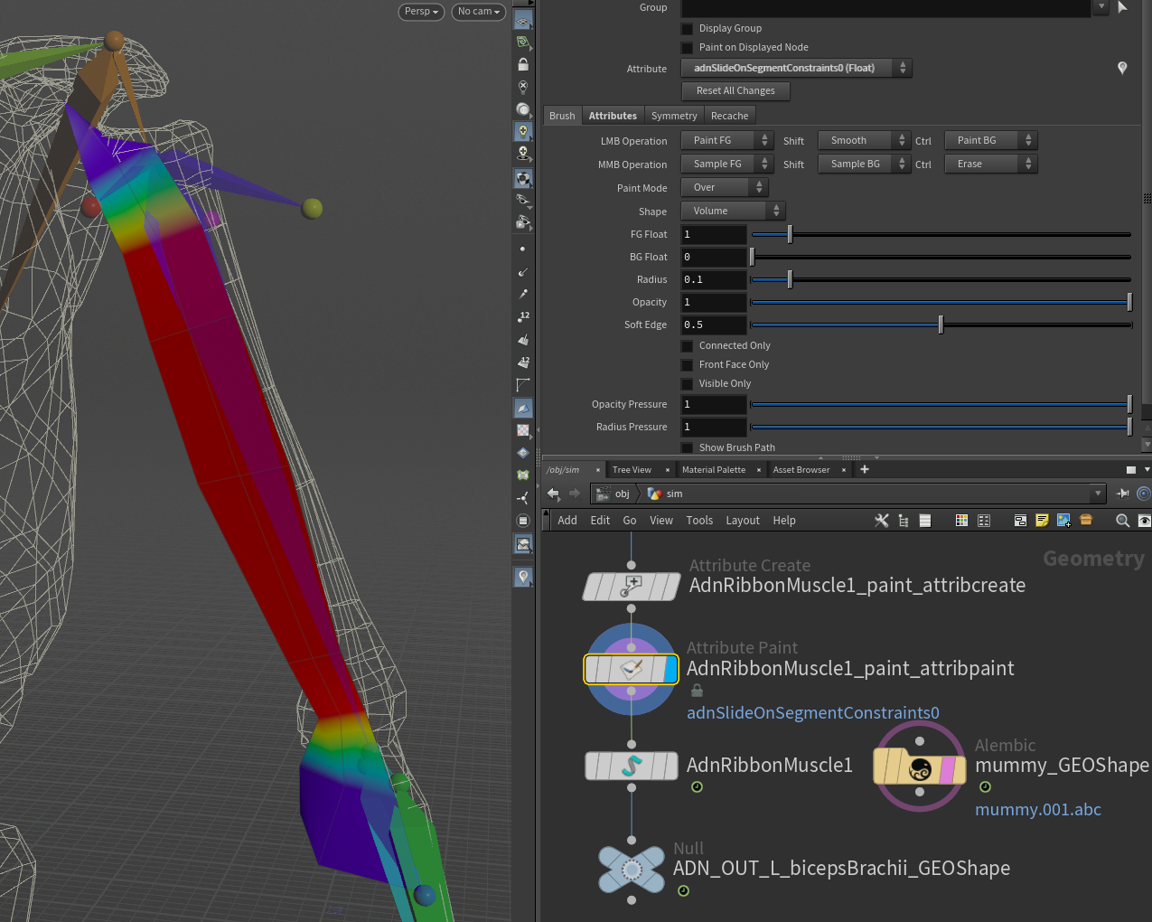
Optionally, add Slide On Segment Constraints. This constraint works in a similar way to Slide On Geometry Constraints, however, instead of providing a geometry, a pair of joints of the rig will be specified representing the segment the muscle will slide on. Press + under the Slide On Segment Constraints collapsible and provide the SOP paths to a pair of joints of the rig (e.g. shoulder and elbow).
Paint Weights
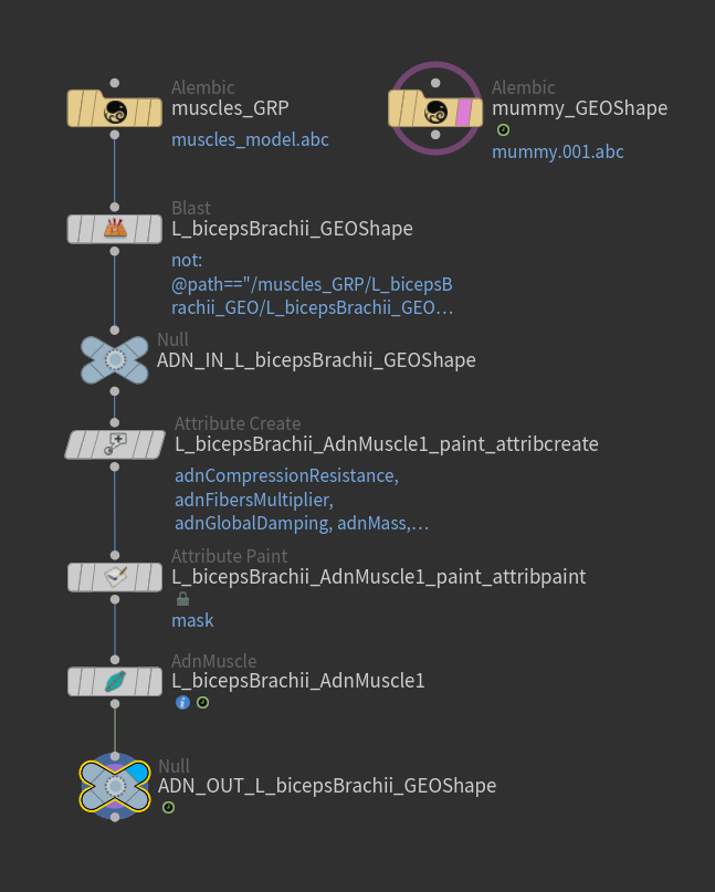
To tweak the point attributes of an AdnMuscle SOP, an attribpaint is needed. To ease the creation and initial configuration of this node, select the AdnMuscle SOP and click on AdonisFX > Utils > Make Paintable. This utility will create an attribcreate node to define the required point attributes and assign their default values followed by an attribpaint node to allow these attributes to be modified. Both nodes are automatically named and properly connected to the AdnMuscle node.
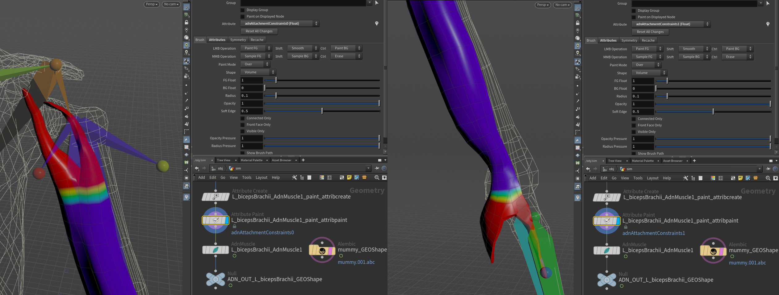
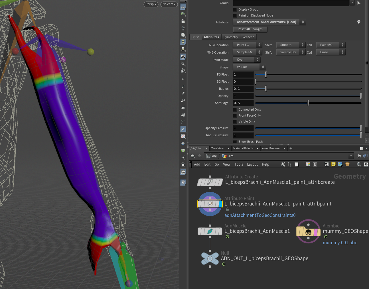
Start by painting attachment weights, painting the influence for each target by selecting the corresponding target from the list and painting its desired influence.
In this example the influence painting for both types of attachment constraint is shown. The different types of attachments can be used together or not depending on the needs of the simulation and the rig setup.
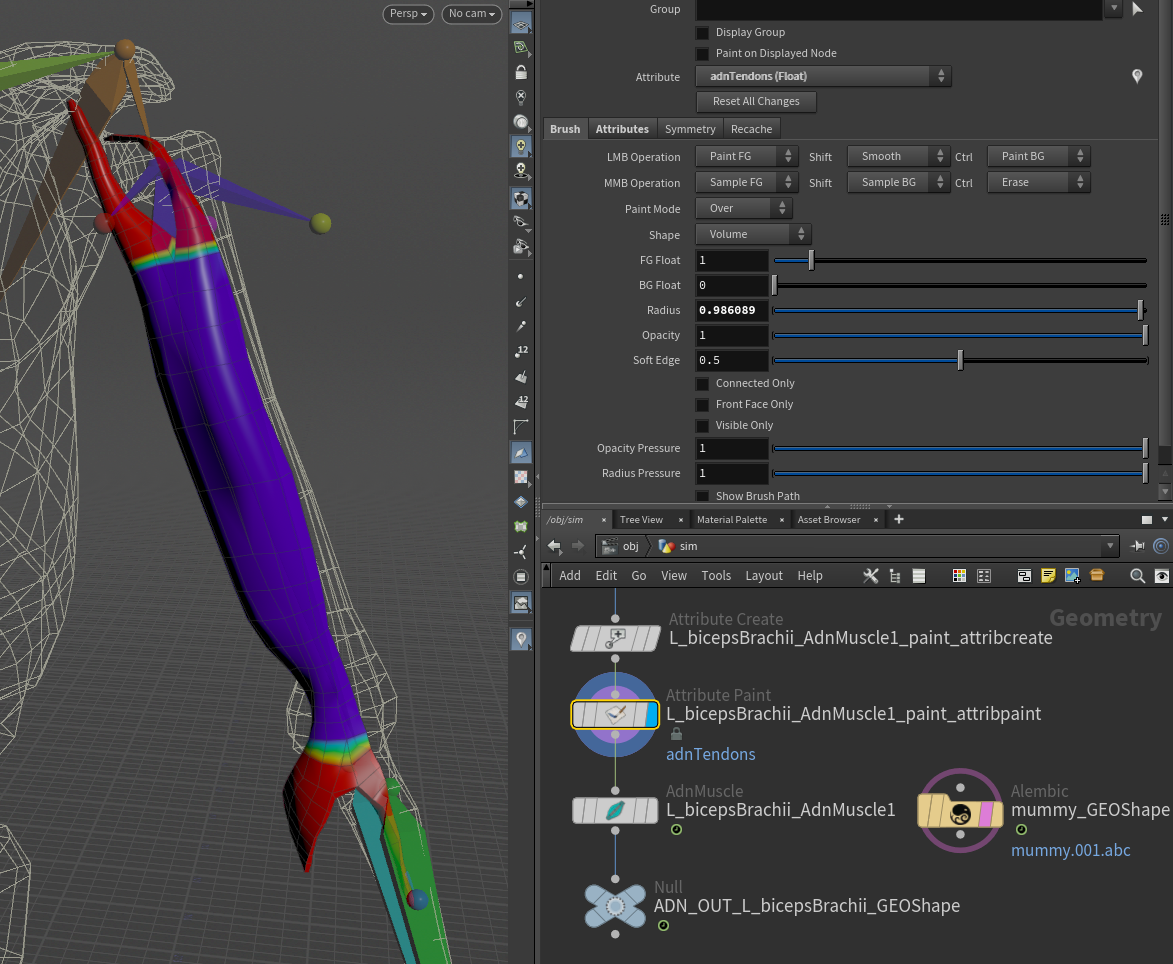
Then, paint the muscle tendon weights, by selecting the Tendon attribute from the Attribute enumerator and paint over the parts of the muscle that should have tendon tissue.
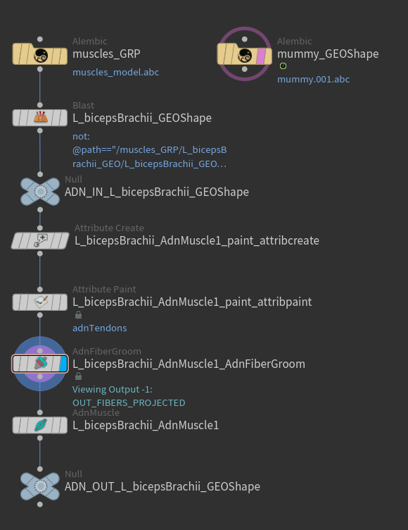
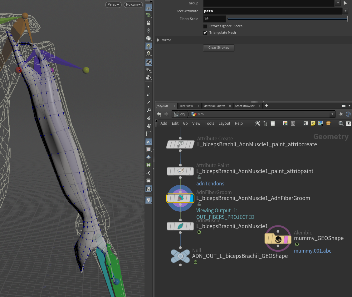
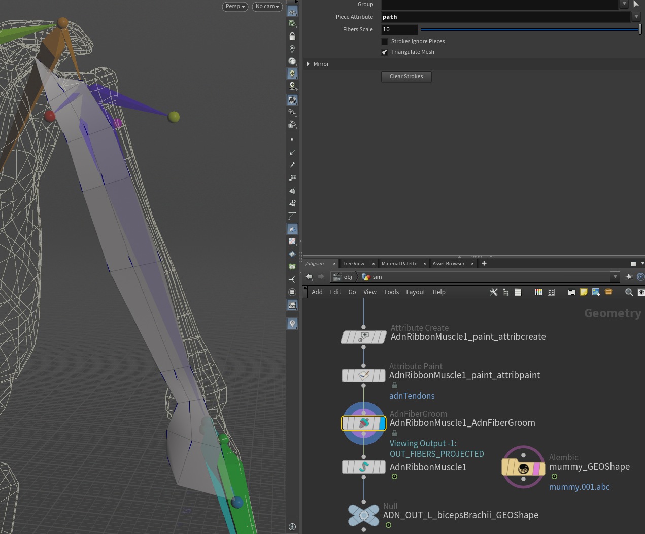
Once tendons are painted it is possible to groom the fibers making use of the AdnFiberGroom HDA. To create this node, press TAB, navigate to the submenu AdonisFX > Utils to find the AdnFiberGroom  HDA type and connect it to the AdnMuscle after the
 attribpaint node.
To visualize, change the fiber size or its color, go to the debug submenu in the SOP node, and customize the color and length of the drawn lines.
To simplify the creation of the AdnFiberGroom HDA, AdonisFX provides Make Groomable utility in AdonisFX > Utils. Use this utility by providing the corresponding AdnMuscle SOP in the selection to create an AdnFiberGroom node that computes the initial fiber directions based on the previously painted adnTendons map. It also allows to further groom and refine the fibers if additional adjustments are needed. The AdnFiberGroom node will be automatically named and properly connected to the muscle SOP node.
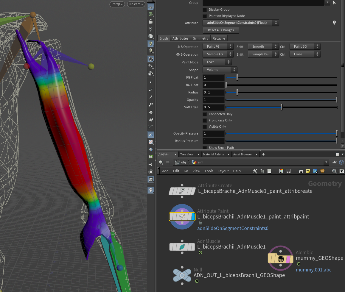
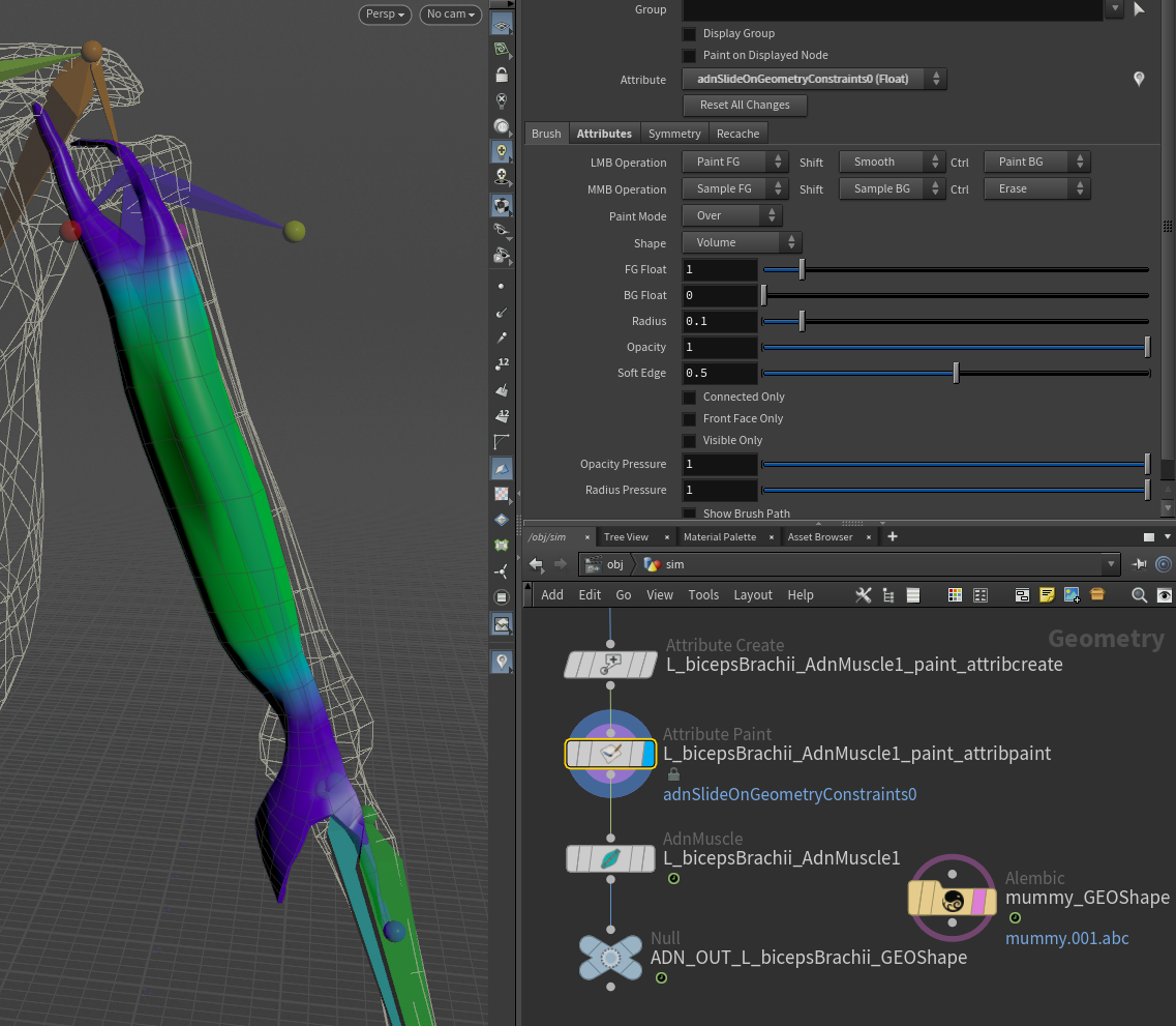
Finally, paint Slide On Segment or Slide On Geometry Constraints (if added). It is recommended to paint only the vertices that are not attached to the rig. In this example, the tendons are painted with a value of 0.0, while the rest of the shape is painted to 1.0 or lower values.
Connect Sensors
To have the muscle changing and responding to external inputs (i.e. the flexion of the arm), AdnSensorRotation can be added to drive the activation of the muscle.
To do this, first create a rotation sensor to compute the elbow angle. Press TAB and navigate to the submenu AdonisFX > Sensors to find the AdnSensorRotation  SOP type.
Then create a rotation locator to visualize the elbow angle. Press TAB and navigate to the submenu AdonisFX > Locators to find the AdnLocatorRotation  SOP type and connect the sensor to the locator.
Once the sensor and locator are created, go to the Input tab of both nodes and provide the SOP paths to the transform nodes from which to extract the transformation information (e.g. shoulder, elbow and wrist joints). Alternatively, use the "Operator Chooser" in the locator and sensor UI to select the correct target nodes containing transform information. Generally these input nodes will be located on the /obj level as a null, joint or rivet.
Now that the locator is created it has to be connected to the deformer. In order to make this connection, use a detail or channel expression. This will allow for the AdnMuscle SOP to pick up the activation attribute from the locator:
- Detail expression:
detail("/obj/geo1/L_adnLocatorRotation_armFlexionShape", "adnActivationRotation", 0)
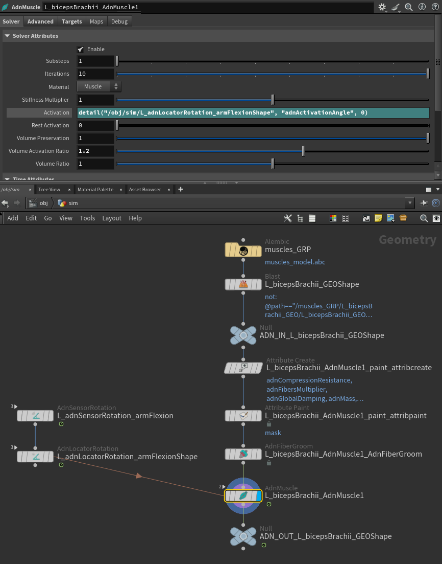
When the elbow is flexed (and therefore the angle from the locator gets smaller) the muscle activation increases, simulating a much more realistic scenario.
To tweak additional parameters of the AdnMuscle deformer, check this page.
AdnRibbonMuscle
The process to set up an AdnRibbonMuscle SOP is very similar to the one of setting up an AdnMuscle. It essentially follows the same steps. Start with the following elements:
- An animation rig or a skeletal mesh (i.e. the mummy) or both.
- A geometry representing the muscle to simulate.
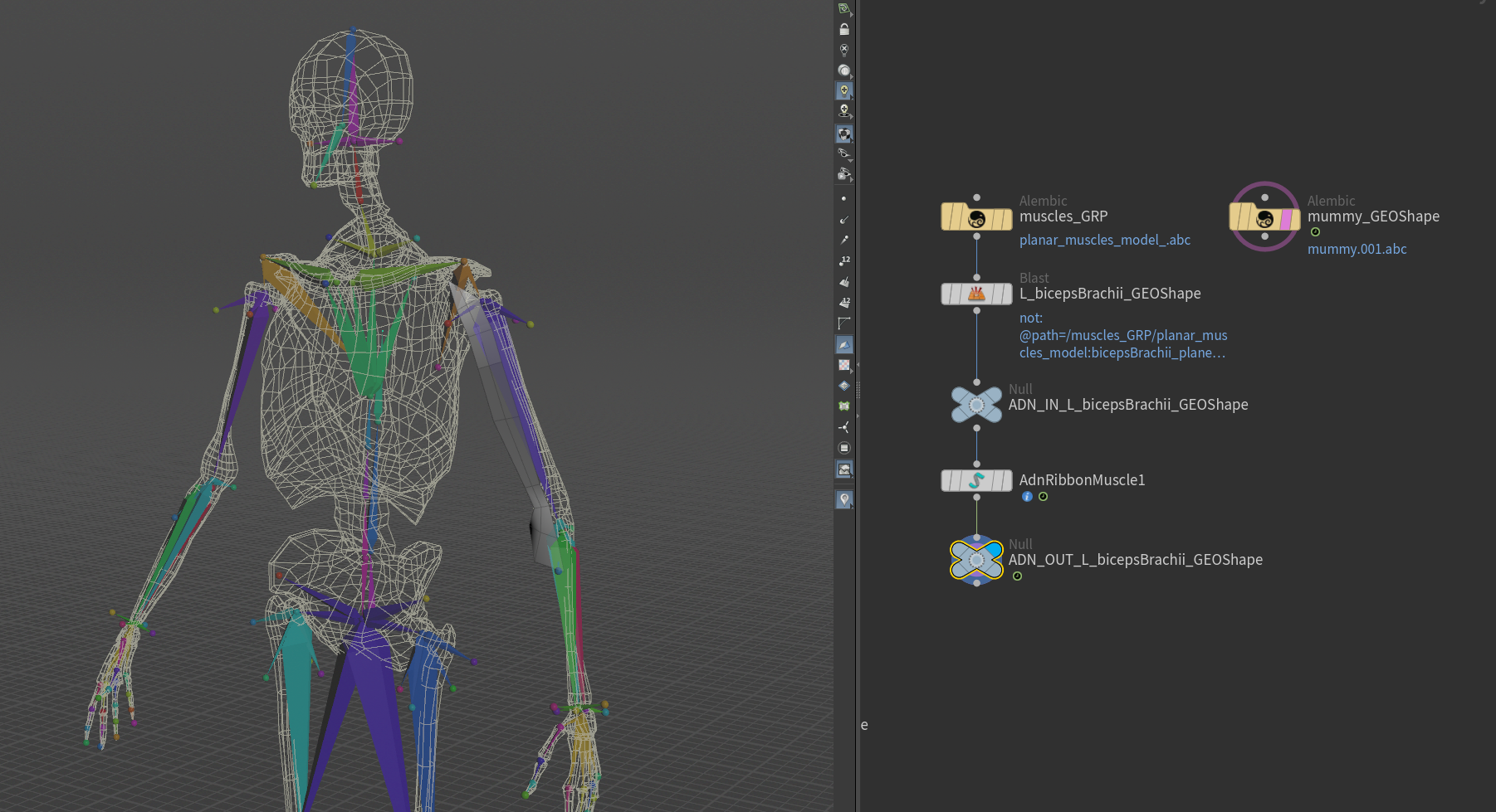
In this case a planar muscle will be simulated corresponding to a biceps, which will yield similar results to the case of the AdnMuscle SOP previously shown.
Create Deformer
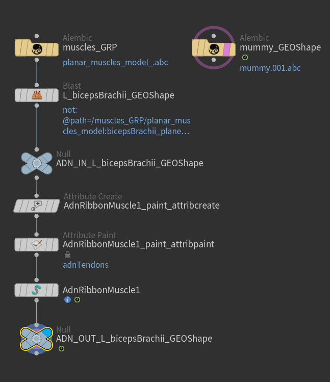
Similar to AdnMuscle, to create the AdnRibbonMuscle SOP, press TAB and navigate to the submenu AdonisFX > Solvers to find the AdnRibbonMuscle  SOP type. Then connect the planar muscle geometry to the input of the AdnRibbonMuscle node.
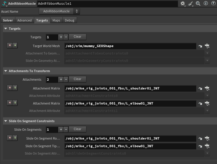
In order to add targets to the muscles, go to the Targets tab on the AdnRibbonMuscle node, press + under the Targets collapsible to add a new entry and provide the path to the SOP containing the target geometry. The geometries added as targets can be used to drive attachment to geometry and slide on geometry constraints.
- Attachments to geometry and slide on geometry constraints are meant to simulate muscle-to-bone and muscle-to-muscle interactions.
- For muscle-to-muscle interactions, only unidirectional relationships are supported. This means that having muscles A and B, it is possible to assign A as target of B or B as target of A, but not the two at the same time.
It is also possible to define attachments to the joints of the rig by pressing + under the Attachments To Transform collapsible and providing the SOP path of the joint to which the muscle will be attached.
Optionally, add Slide On Segment Constraints. This constraint works in a similar way to Slide On Geometry Constraints, however, instead of providing a geometry, a pair of joints of the rig will be specified representing the segment the muscle will slide on. Press + under the Slide On Segment Constraints collapsible and provide the SOP paths to a pair of joints of the rig (e.g. shoulder and elbow).
Paint Weights
To tweak the point attributes of an AdnRibbonMuscle SOP, an attribpaint is needed. To ease the creation and initial configuration of this node, select the AdnRibbonMuscle SOP and click on AdonisFX > Utils > Make Paintable. This utility will create an attribcreate node to define the required point attributes and assign their default values followed by an attribpaint node to allow these attributes to be modified. Both nodes are automatically named and properly connected to the AdnRibbonMuscle node.
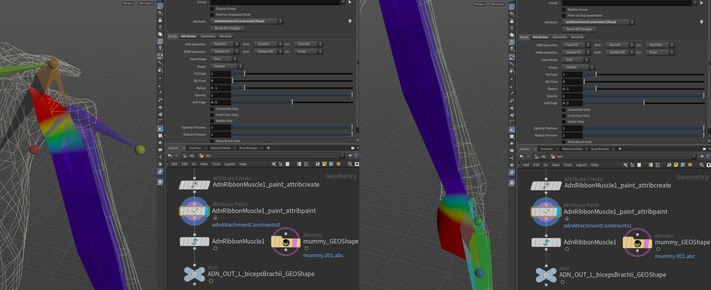
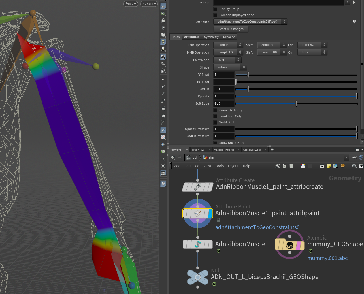
Start by painting attachment weights, painting the influence for each target by selecting the corresponding target from the list and painting its desired influence.
In this example the influence painting for both types of attachment constraint is shown. The different types of attachments can be used together or not depending on the needs of the simulation and the rig setup.
Then, paint the muscle tendon weights, by selecting the Tendon attribute from the Attribute enumerator and paint over the parts of the muscle that should have tendon tissue.
In case the fiber or its color has to be manipulated, go to the debug submenu in the SOP node, and customize the color and length of the drawn lines.

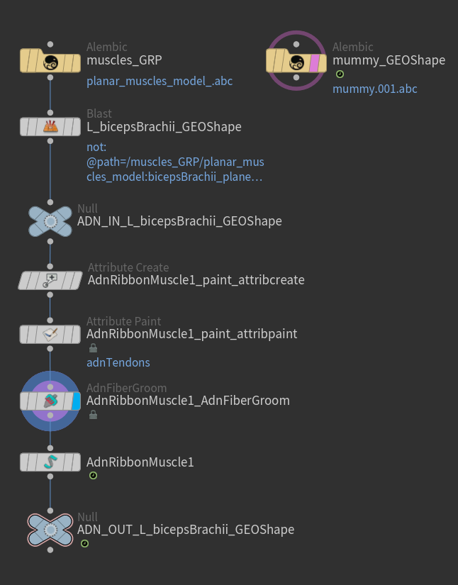
Once tendons are painted it is possible to groom the fibers making use of the AdnFiberGroom HDA. To create this node, press TAB, navigate to the submenu AdonisFX > Utils to find the AdnFiberGroom HDA type and connect it to the AdnRibbonMuscle after the attribpaint node.
To simplify the creation of the AdnFiberGroom HDA, AdonisFX provides Make Groomable utility in AdonisFX > Utils. Use this utility by providing the corresponding AdnRibbonMuscle SOP in the selection to create an AdnFiberGroom node that computes the initial fiber directions based on the previously painted adnTendons map. It also allows to further groom and refine the fibers if additional adjustments are needed. The AdnFiberGroom node will be automatically named and properly connected to the muscle SOP node.
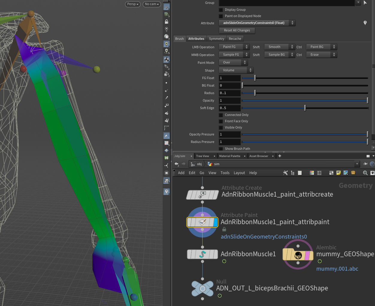
Finally, paint Slide On Segment or Slide On Geometry Constraints (if added). It is recommended to paint only the vertices that are not attached to the rig. In this example, the tendons are painted with a value of 0.0, while the rest of the shape is painted to 1.0 or lower values.
Connect Sensors
The process to connect an AdnSensor to an AdnRibbonMuscle is the exact same as the one followed here.
To tweak additional parameters of the AdnRibbonMuscle SOP, check this page.
AdnGlue
To make the simulated muscles behave more compact and avoid large gaps between them, an AdnGlue node can be used. To create a basic scenario using the AdnGlue node, start with a scene with the following elements:
- A list of simulated muscles to be glued together.
- A merge node that combines the simulated muscles into a single geometry.
The AdnGlue node will take all the simulated muscles merged as a single input.
- AdnGlue requires the input geometry to contain a primitive attribute to be able to identify each muscle.
- If the AdnGlue input does not contain a primitive attribute, click on AdonisFX > Utils > Create Muscle PieceID by having the AdnGlue input selected. This utility will create a
connectivitynode in charge of computing the primitive attribute that will identify each muscle piece.
Create Node
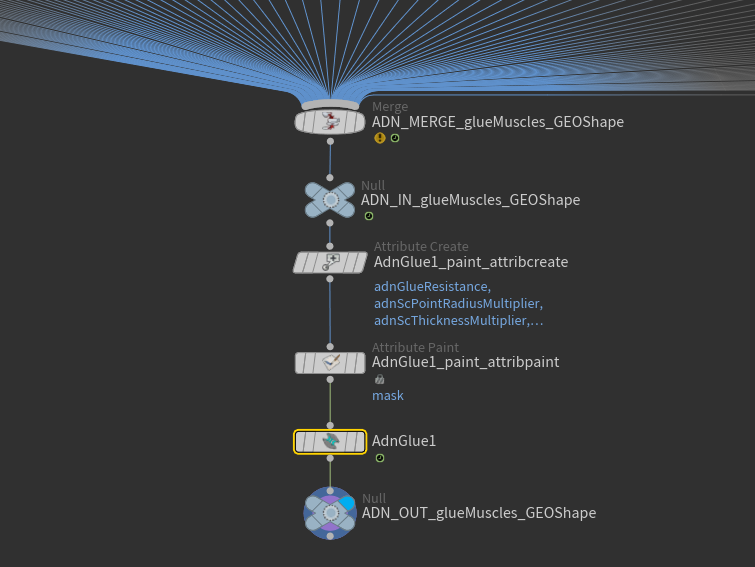
To create the AdnGlue node, press TAB and navigate to the submenu AdonisFX > Solvers to find the AdnGlue  SOP type. Then connect the merged muscles to the AdnGlue input and select the Piece Attribute to allow the SOP to identify each muscle piece.
Input muscles can be added or removed from the existing AdnGlue by connecting or disconnecting them from the merge node. After that, make sure to recook the AdnGlue at preroll start time for this change to take effect.
Adding and removing inputs requires to revisit and update the paintable maps to ensure that the painted values are correct for the new list of geometries.
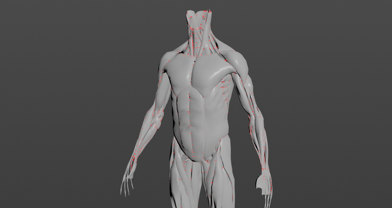
The Max Glue Distance attribute is set to 0.0 by default. Therefore, for the glue constraints to take effect, this value must be adjusted. We recommend enabling the debugger and selecting the Glue Constraints option to inspect the connections created based on the specified Max Glue Distance.
Paint Weights
To tweak the point attributes of an AdnGlue SOP, an attribpaint is needed. To ease the creation and initial configuration of this node, select the AdnGlue SOP and click on AdonisFX > Utils > Make Paintable. This utility will create an attribcreate node to define the required point attributes and assign their default values followed by an attribpaint node to allow these attributes to be modified. Both nodes are automatically named and properly connected to the AdnGlue node.
With the Max Glue Distance previously adjusted, the default values of the paintable maps already allow the node to compute the glue constraints.
The most important maps are adnGlueResistance, adnMaxGlueDistanceMultiplier, and adnShapePreservation, which are flooded with a value of 1.0 by default.
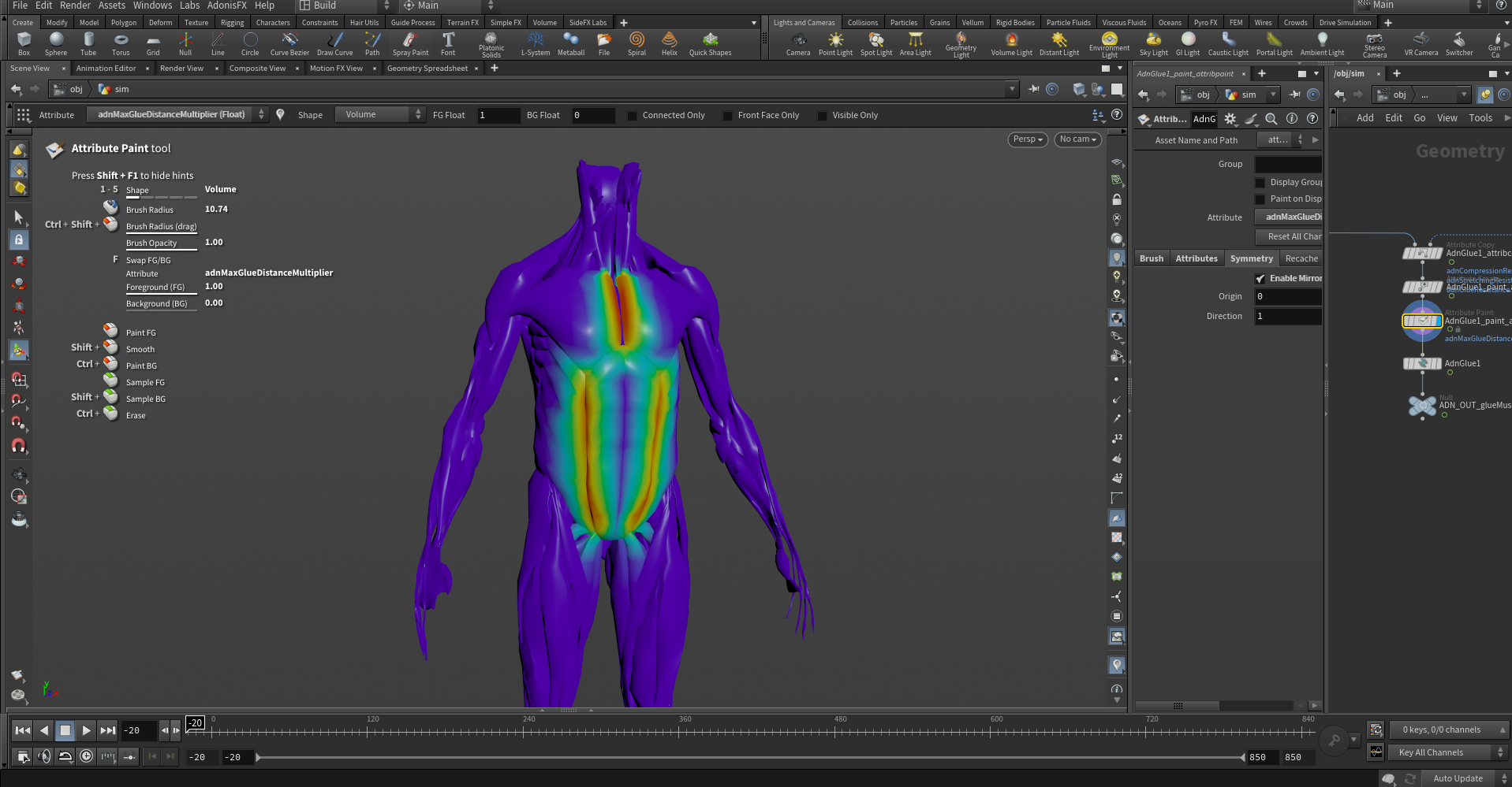
Since the Max Glue Distance is initially the same for all muscles, you may want to adjust it for specific areas. This can be done by painting the adnMaxGlueDistanceMultiplier map. You can paint this map with a value of 0.0 in areas where you do not want the glue constraint to apply. This prevents the creation of the constraint in those areas and can improve the simulation performance.
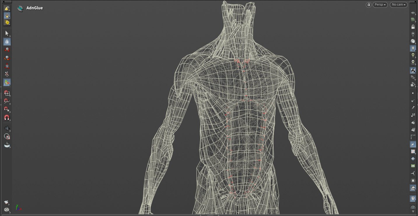
The adnGlueResistance map modulates the strength of the glue constraint. To reduce the effect of the constraint in specific areas, lower the values in this map accordingly. Glue constraints won't be computed for vertices with a weight value of 0.0.
Finally, shape preservation constraints help to maintain the original shape of the muscles and are flooded to 1.0 by default. These constraints are useful if the gluing produces undesired shape on the output mesh. If that is not the case, flood the map to 0.0, which will make the solver run faster. If shape preservation is required, then increase the values on those areas where the shape has been altered during the simulation.
AdnFat
To create a basic scenario using the AdnFat SOP, start with a scene with the following elements:
- A fat tissue mesh without animation or deformation that will become the simulated mesh.
- One base mesh to which the fat layer will be attached to. This could be for example the fascia.
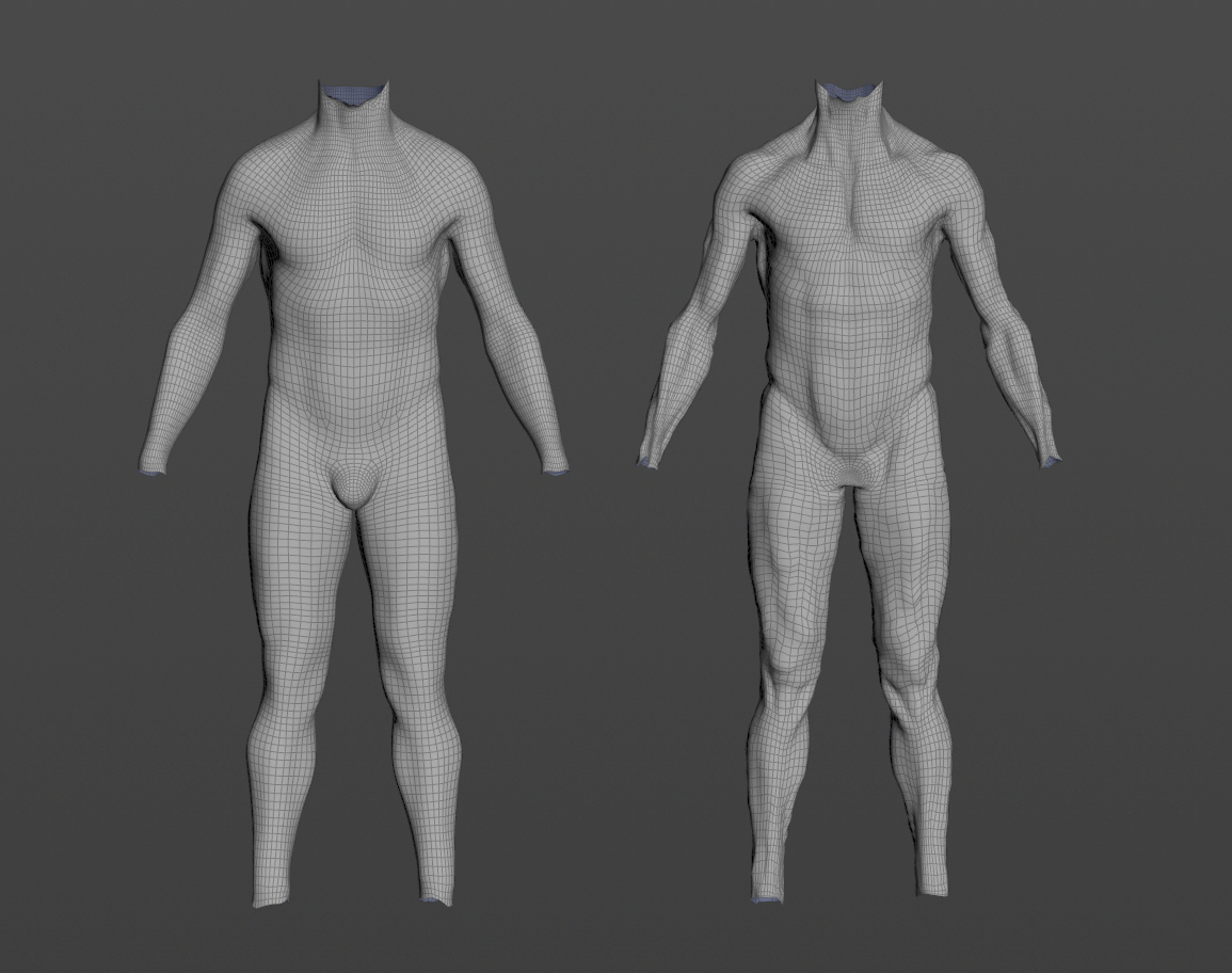
- The base mesh and the fat mesh must have the same vertex count and triangulation.
- Both, the base mesh and the fat mesh must be connected to the AdnFat SOP, otherwise the Fat solver will abort the simulation and the node will display an error.
Create Node
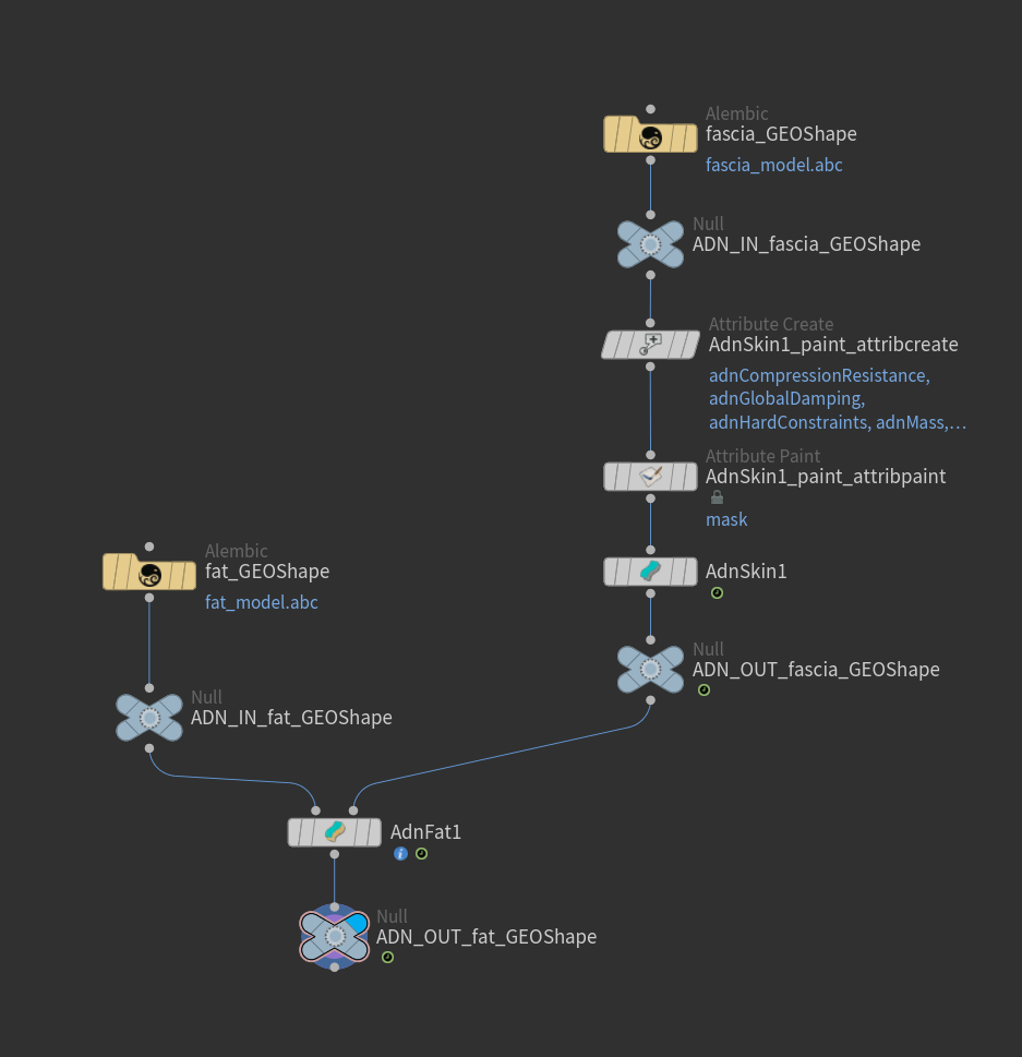
To create the AdnFat SOP, press TAB and navigate to the submenu AdonisFX > Solvers to find the AdnFat  SOP type. Then connect the fat mesh to the first input and the base mesh (e.g. the simulated fascia) to the second input.
After basic configuration, to alter the dynamics of the fat layer (e.g. adding or reducing the jiggle) it is advisable to tweak the main attributes like: Iterations, Substeps, Global Damping Multiplier or the per-constraint stiffness values in the Override Constraint Stiffness section.
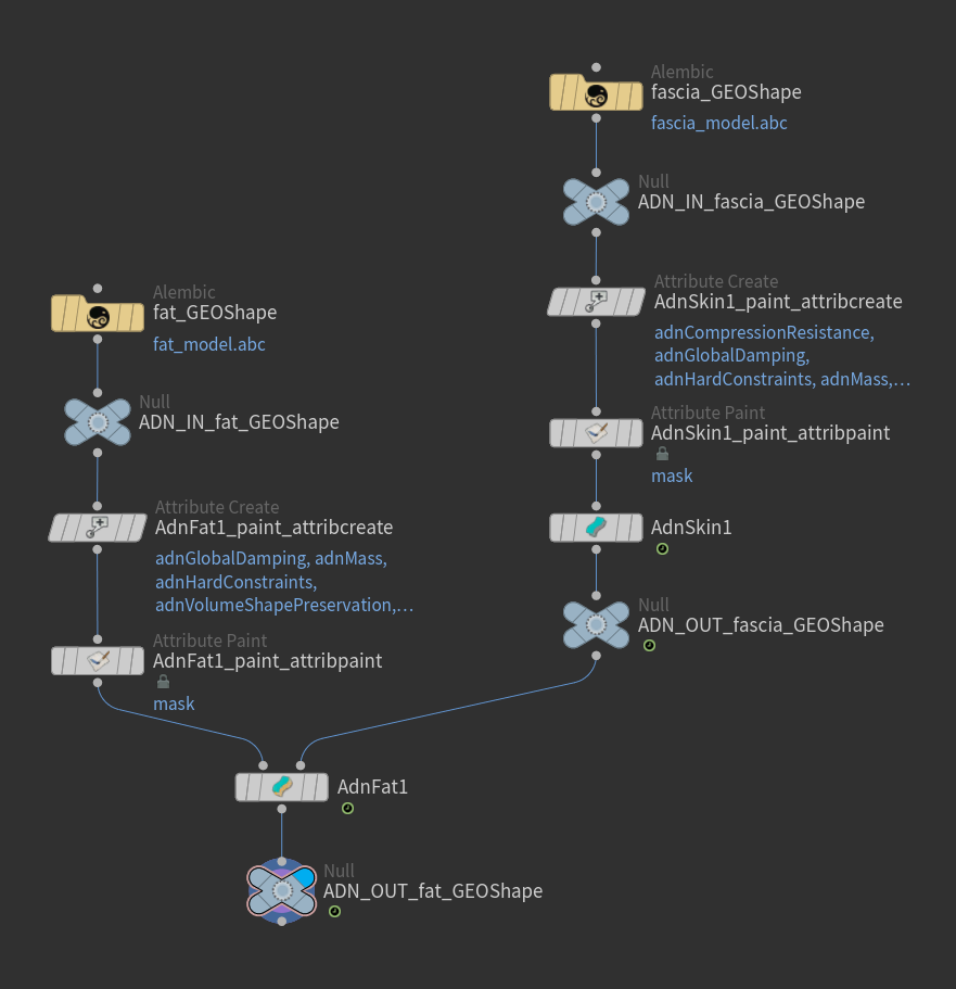
Paint Weights
To tweak the point attributes of an AdnFat SOP, an attribpaint is needed. To ease the creation and initial configuration of this node, select the AdnFat SOP and click on AdonisFX > Utils > Make Paintable. This utility will create an attribcreate node to define the required point attributes and assign their default values followed by an attribpaint node to allow these attributes to be modified. Both nodes are automatically named and properly connected to the AdnFat node.
With the default paint setup provided, the simulation should already create plausible results. However, below we walk you through the three main maps that can be altered to modify the behavior of the fat simulation.
In the case of the AdnFat SOP, the most important paintable maps are adnShapePreservation, adnVolumeShapePreservation and adnHardConstraints. The first two are flooded to 1.0 by default, while the last one is flooded to 0.0.
With adnShapePreservation being flooded to 1.0 by default, the solver will try to maintain the internal structural shape properties of the fat layer. Reducing this map's values can increase the amount of jiggling in the fat tissue in combination with different other parameters. However, reducing the adnShapePreservation map can decrease the fat layer's ability to maintain its shape. Finding the right balance will allow you to get the desired results. It may be advisable to keep this map flooded to 1.0 and reduce its value in areas that don't require any structural shape preservation.
On the other hand, adnVolumeShapePreservation will also try to maintain the shape of the fat volume but with different computation mechanisms than adnShapePreservation. It is advisable to keep this map flooded to 1.0 for best results and only reduce its value (by flooding the mesh) whenever the shape of the fat layer can be altered during simulation.
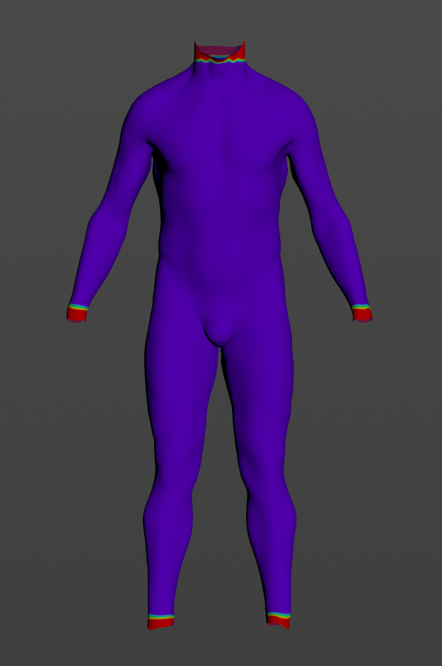
Finally, the adnHardConstraints map provides additional control for stronger attachments to the base mesh. In most cases, this map can be left unmodified so that the solver does not apply this constraint. However, when there is a large enough gap between the simulated mesh and the base mesh in areas close to edges (e.g. neck, wrists or ankles), it can be useful to paint them with a value of 1.0 to mitigate excessive motion.
AdnSkin
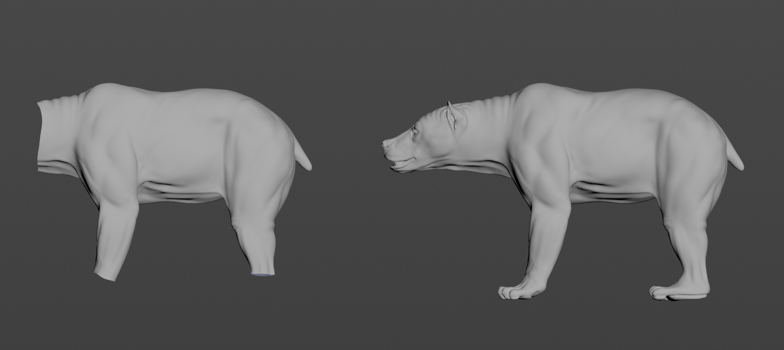
To create a basic scenario using the AdnSkin SOP, start with a scene with the following elements:
- A skin mesh without animation or deformation.
- One or more target meshes with deformation.
Create Deformer
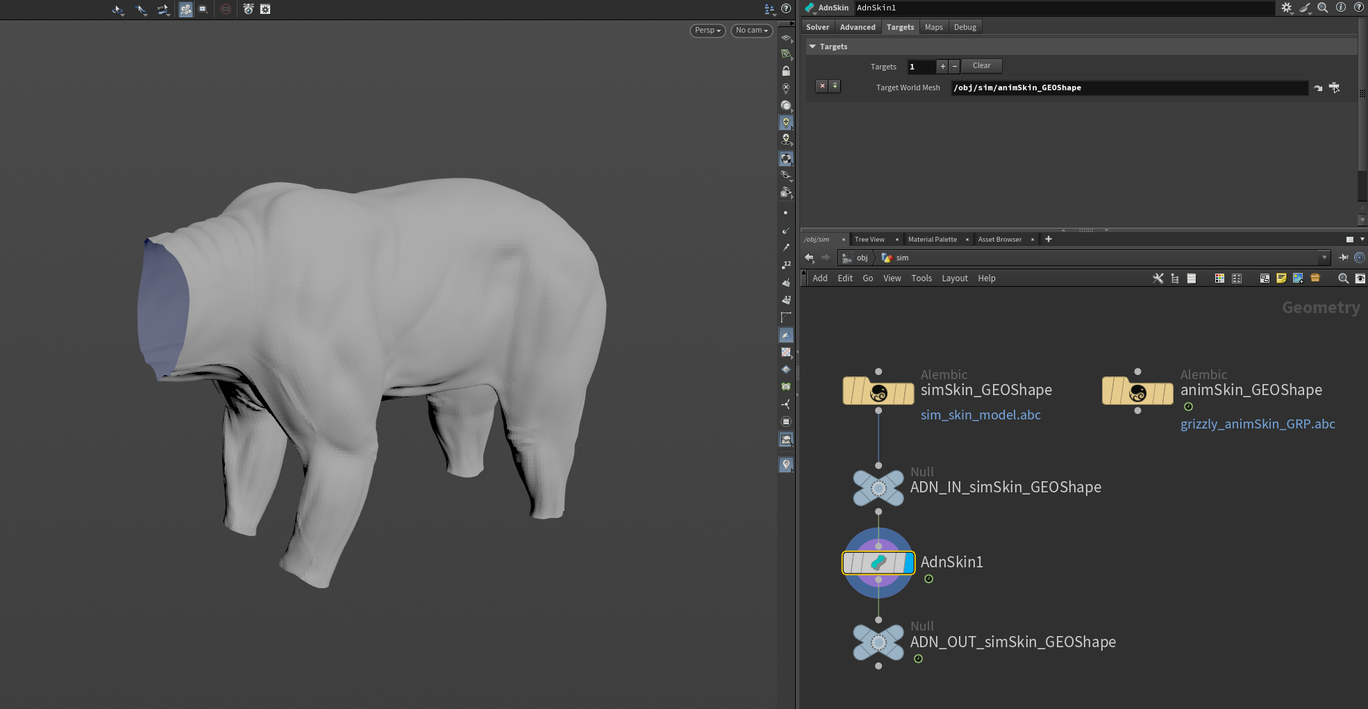
To create the AdnSkin node, press TAB and navigate to the submenu AdonisFX > Solvers to find the AdnSkin  SOP type. Then connect the skin mesh to the AdnSkin input.
To add target mesh(es), go to the Targets tab on the AdnSkin node, press + to add a new target entry and set the path to the SOP node containing the target geometry to the Target World Mesh parameter.
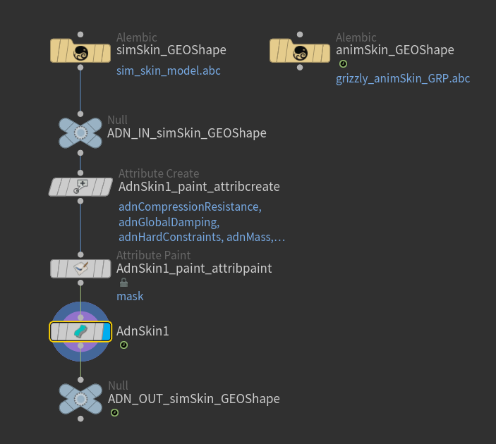
Paint Weights
To tweak the point attributes of an AdnSkin SOP, an attribpaint is needed. To ease the creation and initial configuration of this node, select the AdnSkin SOP and click on AdonisFX > Utils > Make Paintable. This utility will create an attribcreate node to define the required point attributes and assign their default values followed by an attribpaint node to allow these attributes to be modified. Both nodes are automatically named and properly connected to the AdnSkin node.
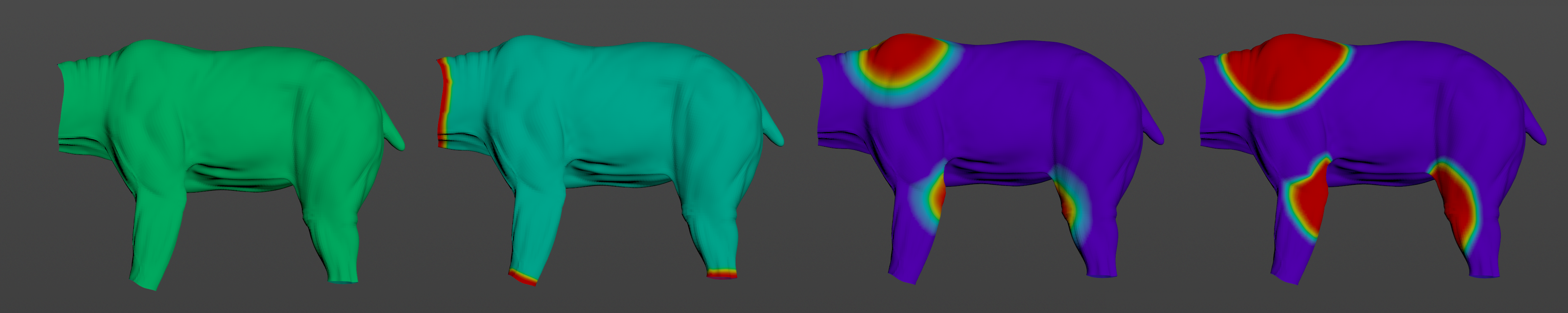
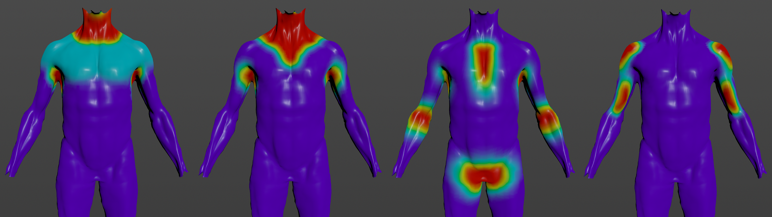
Start by painting the adnSoftConstraints map. Flood this map with a low value of 0.45 to have a uniform distribution of soft constraints. This will help the skin to follow the target mesh.
Now paint adnHardConstraints in two steps. First, flood this weight to a value of 0.3 to help the skin (together with the soft weights) to follow the target mesh. Then, set the edges to 1.0 to attach them strongly to the target mesh.
Then select the adnSlideConstraints attribute and paint weights only in those areas where the skin is supposed to slide over the target mesh. In this case, focus these weights over the scapulas and the joints of the limbs.
Finally, select the adnMaxSlidingDistanceMultiplier attribute and paint weights to 1.0 only in the sliding areas. This will ensure that the vertices with sliding properties will get assigned with the maximum sliding distance (defined by the Max Sliding Distance attribute), while the non-sliding vertices will get assigned with 0.0 sliding distance, which will improve the performance of the simulation.
With this basic paint setup the AdnSkin deformer will already show plausible results, expected of the skin to the target mesh. However, the possible parameters and tweaks to display high fidelity dynamics can be seen in the documentation for AdnSkin.
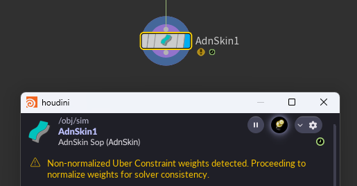
Soft, hard, and slide constraints form a compound constraint known as Uber constraint. Therefore, the sum of the weights for these three constraint types must not exceed 1.0. If the total weight is higher, the solver will still run the simulation because an internal normalization is applied. However, the AdnSkin SOP node will display a warning indicating that the weights will be normalized (see Figure 38).
AdnRelax
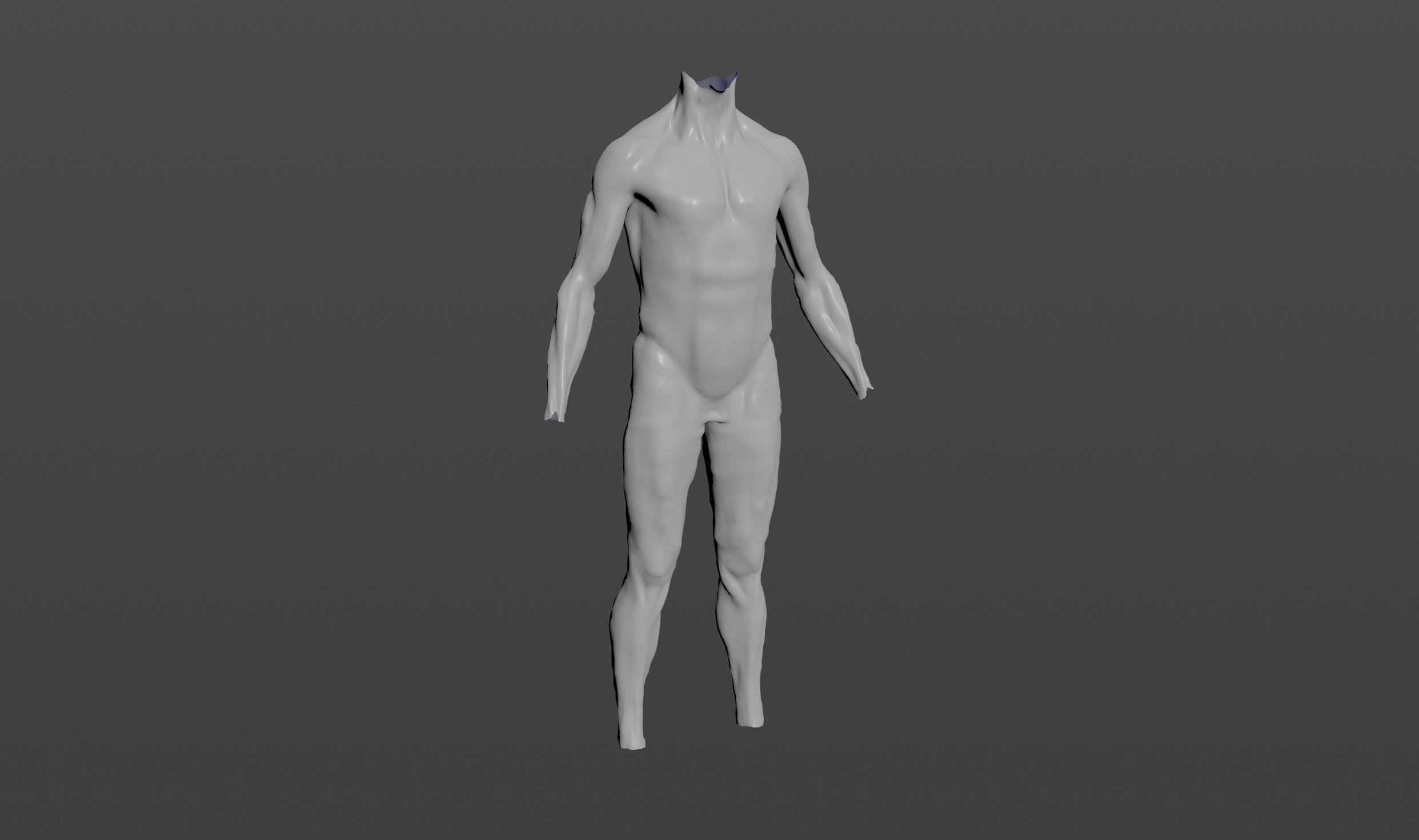
To create a basic scenario using the AdnRelax SOP, start with a scene with a mesh to apply the relaxation onto. This could be for example the simulated fascia layer.
Create Node
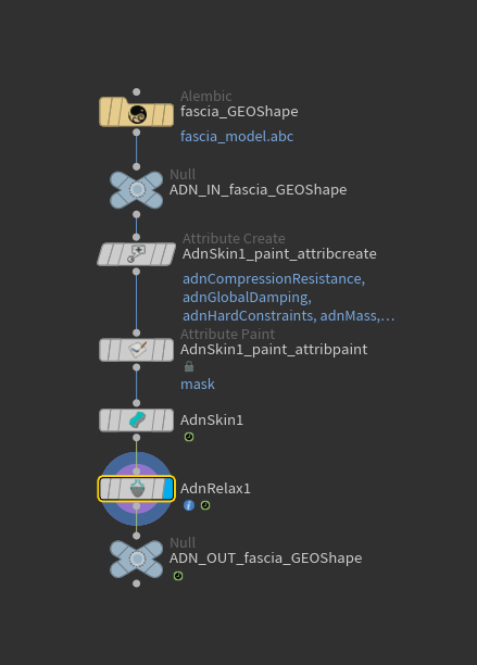
To create the AdnRelax SOP:
- Go to the geometry context of the rig containing the geometry to apply the SOP to.
- Press TAB and navigate to the submenu AdonisFX > Deformers to find the AdnRelax
 SOP type.
 - Create it and connect the geometry to the input.
- Increase the number of iterations to see the effect of the relaxation algorithm.
Paint Weights
The AdnRelax paintable maps default to 1.0 if the point attributes are not found in the input source. They act as multipliers for the main relax parameters (i.e., Smooth, Relax, Push In Ratio, and Push Out Ratio). Therefore, the relaxation algorithm will be applied uniformly over the entire mesh unless the maps are adjusted.
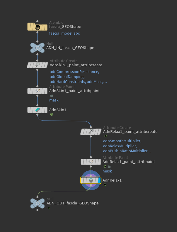
To tweak the point attributes of an AdnRelax SOP, an attribpaint is needed. To ease the creation and initial configuration of this node, select the AdnRelax SOP and click on AdonisFX > Utils > Make Paintable. This utility will create an attribcreate node to define the required point attributes and assign their default values followed by an attribpaint node to allow these attributes to be modified. Both nodes are automatically named and properly connected to the AdnRelax node.
Now the deformed mesh can be refined in specific areas by modifying the paintable attributes. Flood a specific map to 0.0 and paint higher values in the areas where the relaxation algorithm should take effect.
The smoothing is modulated by the adnSmoothMultiplier map. Keep it flooded to 1.0 to smooth the surface of the entire mesh, or flood it to 0.0 and paint values of 1.0 in the areas that need smoothing.
The relaxation is modulated by the adnRelaxMultiplier map. Keep it flooded to 1.0 to relax the surface of the entire mesh, or flood it to 0.0 and paint values of 1.0 in the areas that need relaxation.
After smoothing and relaxation are applied, the mesh may lose some volume or detail. Push in and push out adjustments can be used to recover volume and detail. The attributes Push In Ratio and Push Out Ratio are set to 0.0 by default, to apply these adjustments, increase their values. Then, use the adnPushInRatioMultiplier and adnPushOutRatioMultiplier maps to modulate the specific areas where these adjustments will take effect.
If a specific area shows volume loss, flood the adnPushOutRatioMultiplier to 0.0 and paint values of 1.0 in areas that need to recover volume so that the push out adjustment moves the vertices outward along their normals.
If a specific area has lost detail, flood the adnPushInRatioMultiplier to 0.0 and paint values of 1.0 in areas that need more detail so that the push in adjustment moves the vertices inward, opposite to the direction of their normals.
AdnPush
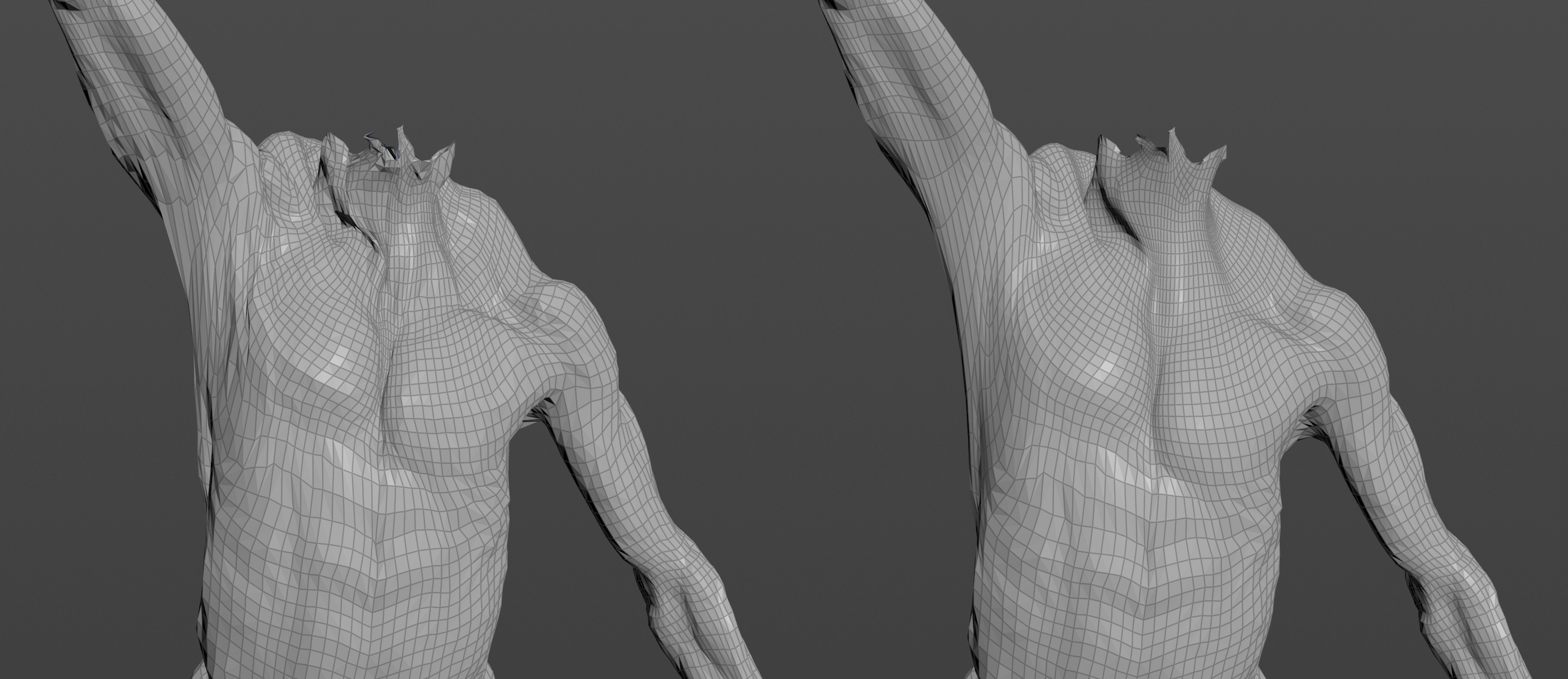
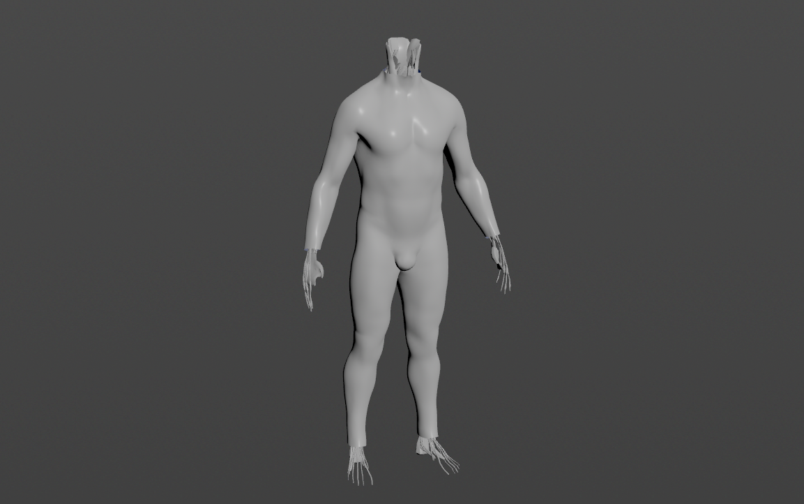
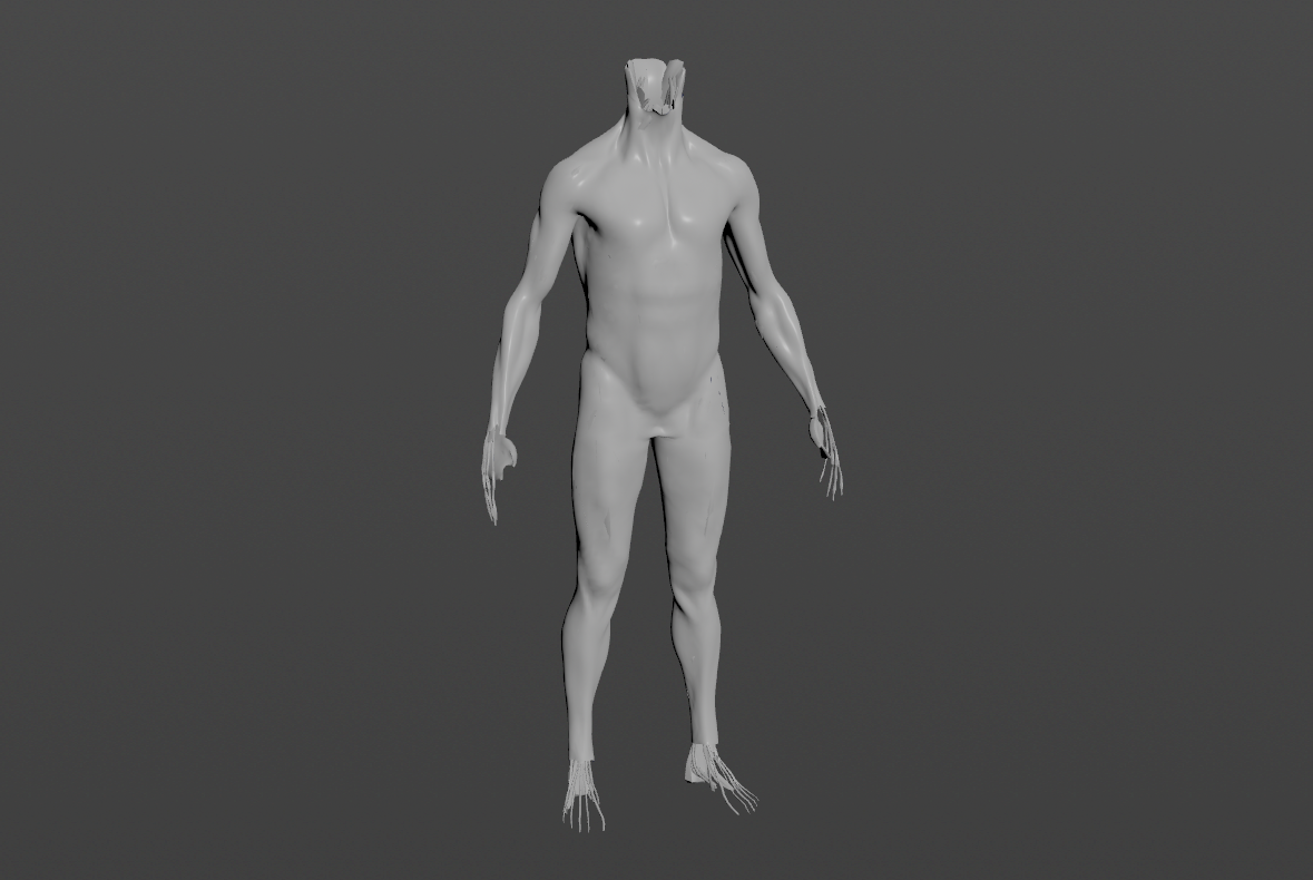
A good example of a use case for the AdnPush SOP is to generate the internal fascia of a character from the outer skin mesh. To prepare this scenario, start with the skin mesh at rest, duplicate it and rename it.
Create Node
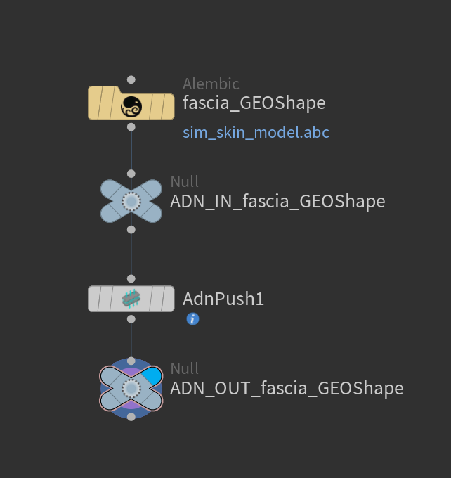
To create the AdnPush SOP, press TAB and navigate to the submenu AdonisFX > Deformers to find the AdnPush  SOP type and connect the copy of the skin mesh at rest to the AdnPush input. Then, set a negative value to the Push Length parameter to apply the push effect inwards (e.g. -2.0).
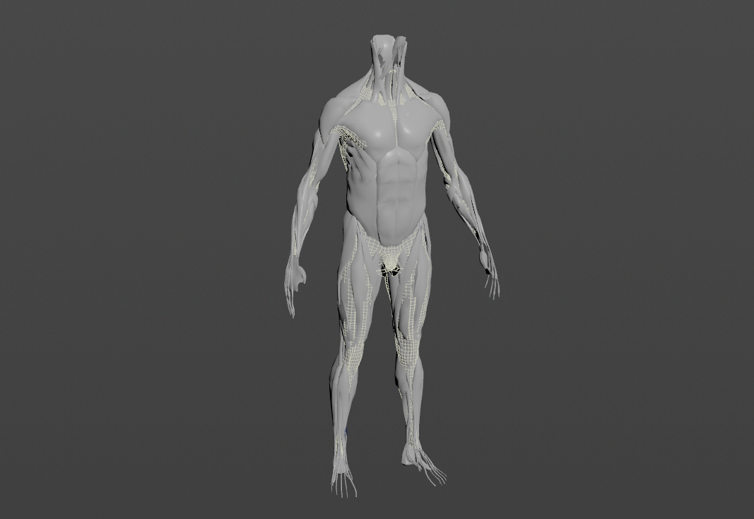
Keeping the muscle layer visible is helpful to drive the configuration of the AdnPush settings, especially the paintable maps. It is expected and intended to get intersections with the muscle layer at this point. Those intersections will be fixed by tweaking the maps.
Paint Weights
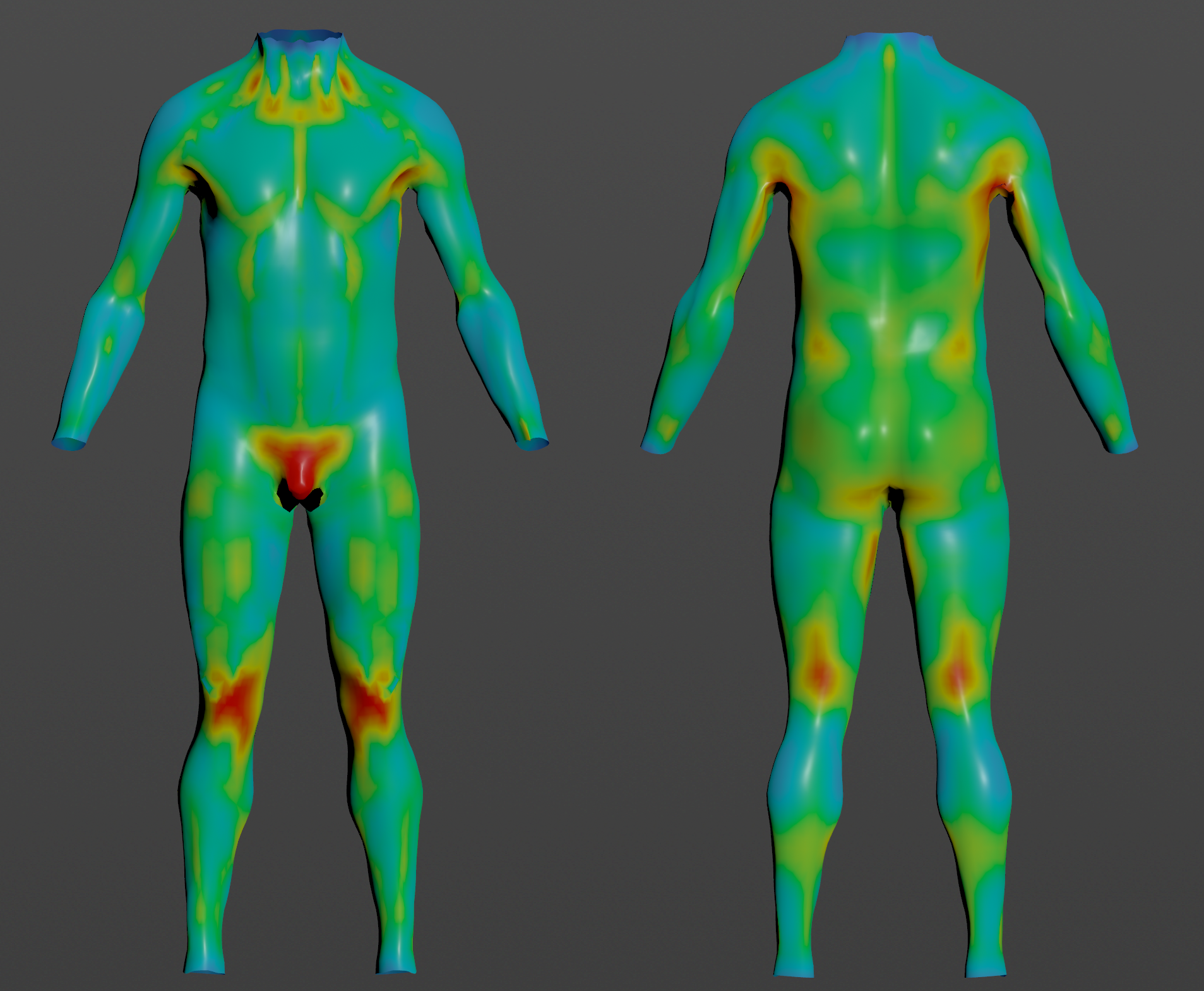
To tweak the point attributes of an AdnPush SOP, an attribpaint is needed. To ease the creation and initial configuration of this node, select the AdnPush SOP and click on AdonisFX > Utils > Make Paintable. This utility will create an attribcreate node to define the required point attributes and assign their default values followed by an attribpaint node to allow these attributes to be modified. Both nodes are automatically named and properly connected to the AdnPush node.
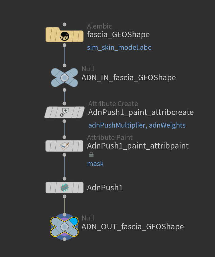
The adnPushMultiplier and adnWeights maps are flooded to 1.0 by default. The push multiplier is meant to modulate the amount of push across the entire mesh as it is the map that multiplies the global Push Length at each point. In the example with the muscle layer visible, this map can be tweaked to remove the intersections.
AdnSkinMerge
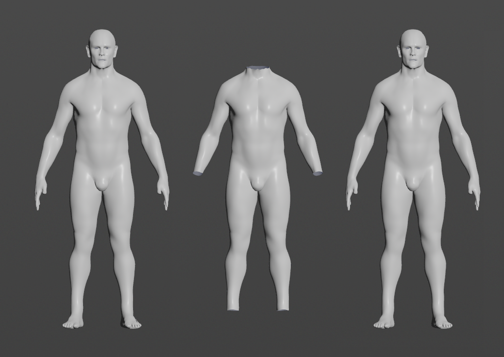
To create a basic scenario using the AdnSkinMerge SOP, start with a scene with the following elements:
- One or more animation meshes with deformation.
- One or more simulation meshes, for example with an AdnSkin SOP applied and properly configured.
- A final mesh without animation or deformation.
The AdnSkinMerge SOP will be applied to the final mesh which will be the result of blending the animation and simulation meshes.
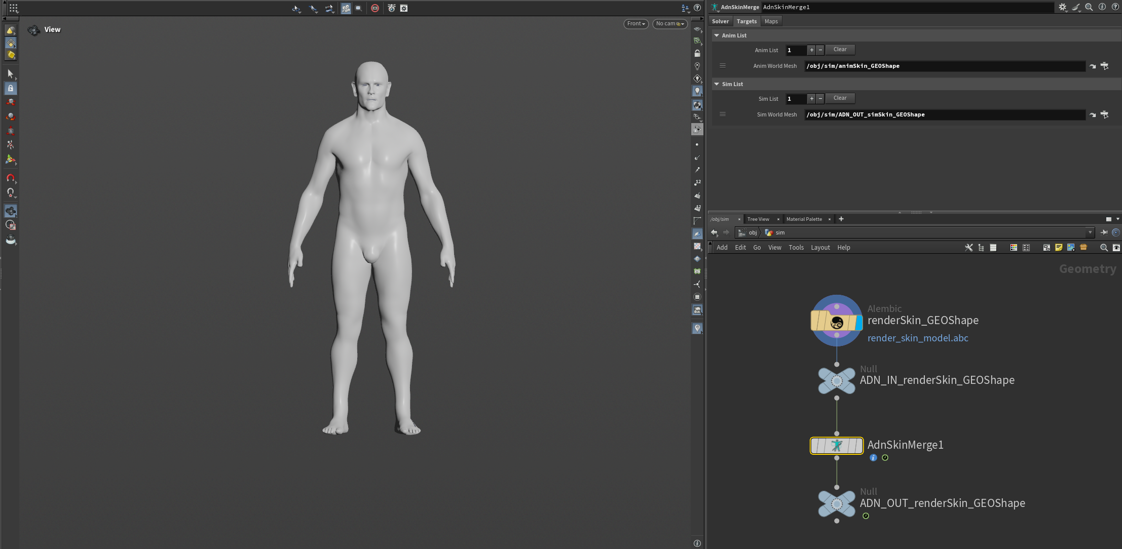
Create Node
To create the AdnSkinMerge node, press TAB and navigate to the submenu AdonisFX > Solvers to find the AdnSkinMerge  SOP type. Then connect the final mesh to the AdnSkinMerge input and go to the Targets tab to provide the anim and sim meshes. Make sure the initialization time corresponds to the start time where all the geometries are in rest pose.
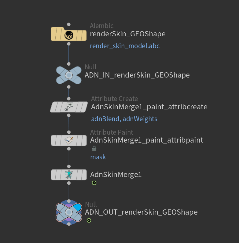
Paint Weights
To tweak the point attributes of an AdnSkinMerge SOP, an attribpaint is needed. To ease the creation and initial configuration of this node, select the AdnSkinMerge SOP and click on AdonisFX > Utils > Make Paintable. This utility will create an attribcreate node to define the required point attributes and assign their default values followed by an attribpaint node to allow these attributes to be modified. Both nodes are automatically named and properly connected to the AdnSkinMerge node.
Once the attribpaint node is created the weights can be painted to blend the animation and simulation meshes into the final mesh.
The adnBlend attribute represents the level of influence of the simulated mesh: a value of 0.0 makes the vertices follow the animated inputs, while a value of 1.0 makes the vertices follow the simulated inputs.
To have a smooth transition from the simulated mesh to the animated mesh, smooth the painting in the areas near the edges between the simulation and animation meshes.
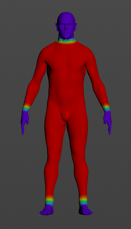
With this basic paint setup the AdnSkinMerge SOP will now show the results of skin simulation transferred to the final mesh.
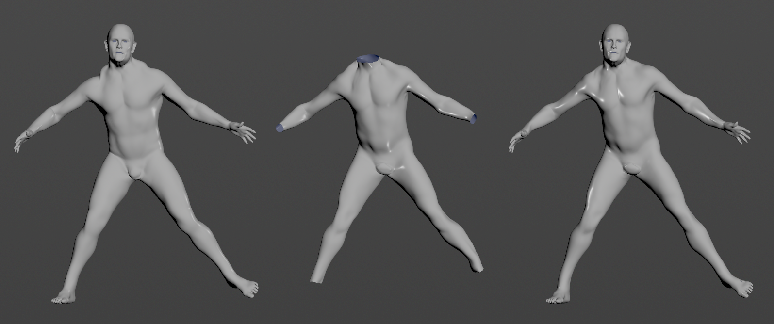
AdnSimshape
To create a basic scenario using the AdnSimshape SOP, start with a scene with the following elements:
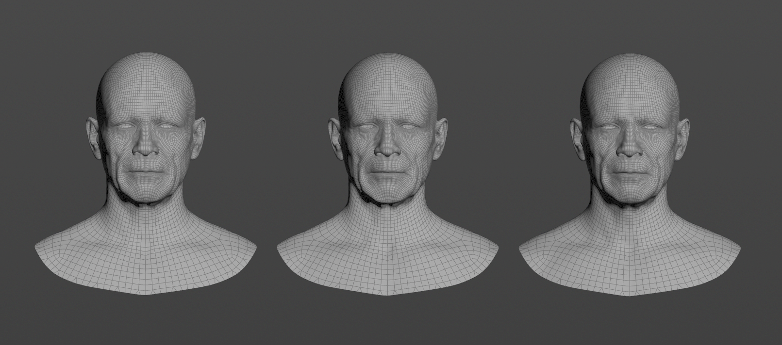
- An animated facial mesh to which to apply the SOP.
- A rest mesh.
- Optionally, a deformation mesh with only the facial deformation (no animation) to allow muscle activations.
All these meshes must have the same number of vertices and correspond to the same facial model.
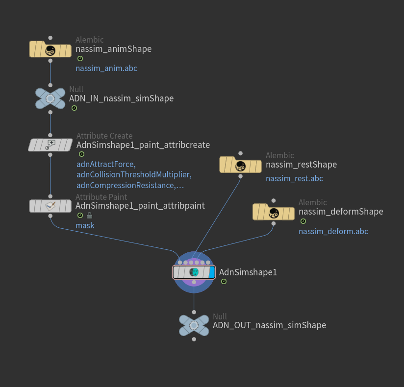
Create Node
To create the AdnSimshape node, press TAB and navigate to the submenu AdonisFX > Solvers to find the AdnSimshape  SOP type. Then connect the animated mesh to the first input, the rest mesh to the third input and the deformation mesh to the fourth input.
Paint Weights
To tweak the point attributes of an AdnSimshape SOP, an attribpaint is needed. To ease the creation and initial configuration of this node, select the AdnSimshape SOP and click on AdonisFX > Utils > Make Paintable. This utility will create an attribcreate node to define the required point attributes and assign their default values followed by an attribpaint node to allow these attributes to be modified. Both nodes are automatically named and properly connected to the AdnSimshape node.
The most important paintable map is the adnAttractForce as this is the value that dictates how much of each simulated vertex should follow the animation. This value is flooded by default to 1.0, meaning that by default the simulated mesh will follow the animation completely, without displaying dynamics.
In high deformation areas, such as around the mouth or under the eyes, add medium to low values (in this case painting with a value of 0.4).
Painting lower Attraction Force weights in meatier areas of the face, such as under the neck or in the cheeks to show more dynamics in these regions. In this case a value of 0.15 will be applied.
The lowest values (0.1 in this case) will be applied to the area under the jaw where dynamics will appear the most.
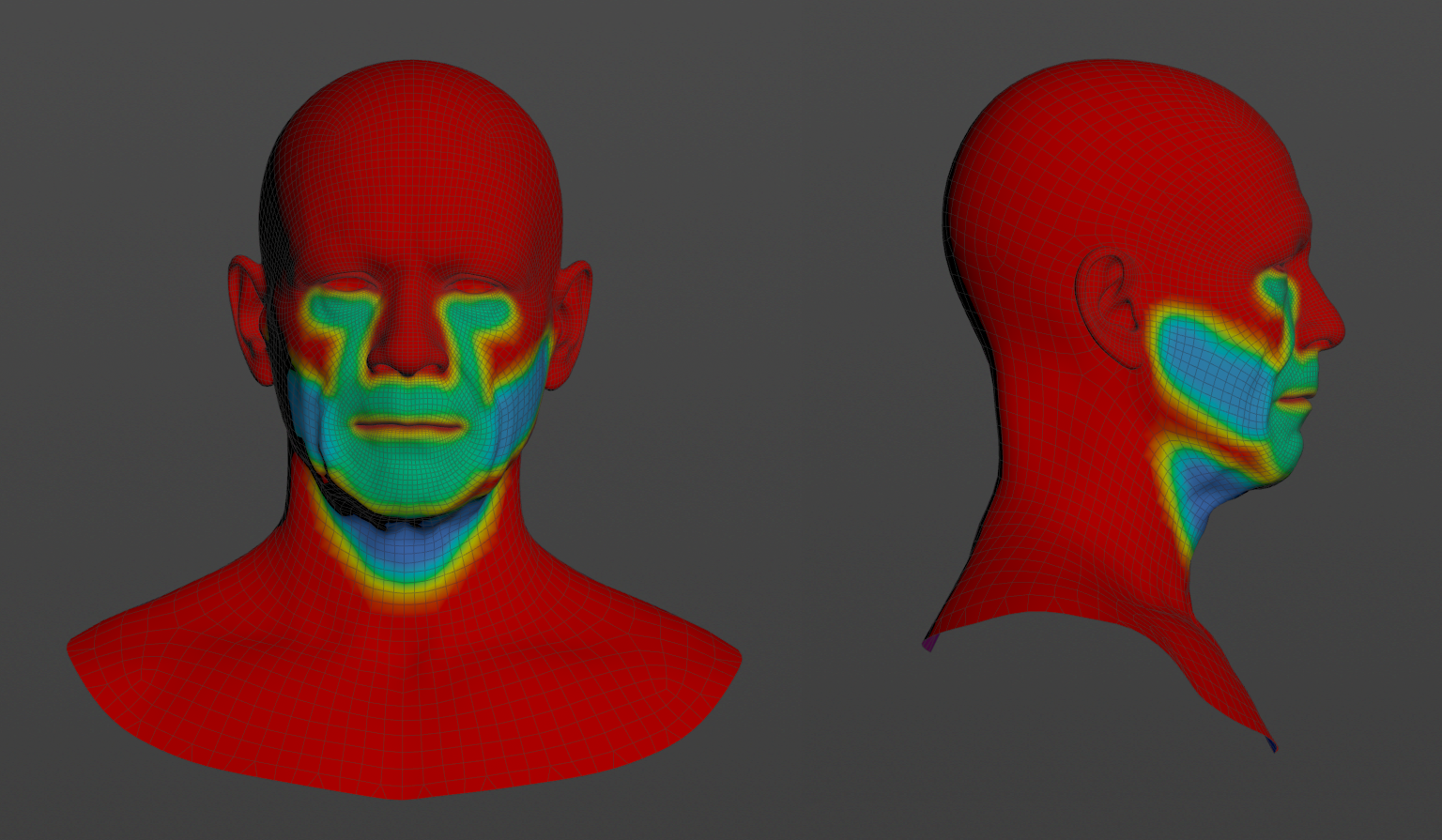
After painting similar weights to the ones displayed and pressing playback to check the animation, realistic dynamics should be simulated in the face. Many more paintable weights to better customize and tweak face dynamics are available and fully explained in the documentation for AdnSimshape.
Add muscle activations
To further have a realistic depiction of facial dynamics, facial muscle activations can be simulated. The AdnSimshape SOP has two methods of handling muscle activations:
- AdonisFX Muscle Patches file.
- Edge Evaluator Node.
Refer to this section to see how to use Muscle Patches files. However, in this example, it is taken advantage of the AdnEdgeEvaluator SOP. The process is the following:
- Press TAB and navigate to the submenu AdonisFX > Utils to find the AdnEdgeEvaluator
 SOP type.
 - Connect the deformation mesh to the first input and the rest mesh to the second input.
- Cook the AdnEdgeEvaluator node and the
adnCompressionpoint attribute will be written into the geostream. - Transfer the
adnCompressionpoint attribute to the geostream of the first input of AdnSimshape with the nameadnActivation. - Select the Plug Values options in the Activation Mode dropdown located in the Muscles Activation Settings section of the AdnSimshape node.
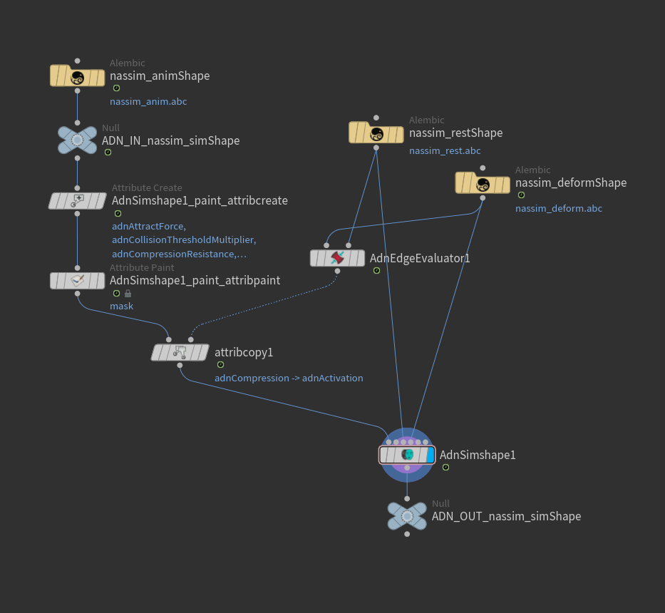
The output activation values can be debugged by checking the option Write Out Activation and visualizing the adnOutActivation point attribute.

