AdnSkin is a Houdini SOP for fast, robust and easy-to-configure skin simulation for digital assets. Thanks to the combination of internal and external constraints, the SOP can produce dynamics that allow the skin mesh to realistically react to the deformations of internal tissues (e.g. muscles, fascia) over time.
The influence these constraints have on the simulated mesh can be freely modified by painting specific point attributes or by regulating several multipliers exposed in the Parameter Template of the SOP. Besides the maps and multipliers there are many other parameters to regulate the skin's dynamics and behavior to a wide array of options.
The AdnSkin SOP is of great simplicity to set up and apply to a mesh within a Houdini scene. The way this deformer works is by applying simulation on top of the skin mesh (simulated mesh) which will be directly coupled to its target meshes (with deformation over time).
To create an AdnSkin the following inputs must be provided:
Targets (T): List of geometries to drive the simulation mesh (e.g. the glued muscles to simulate the fascia, or the fat to simulate the skin).
Skin Mesh (S): Mesh to apply the SOP onto.
The process to create the AdnSkin is:
Go to the geometry context of the rig containing the geometry to simulate.
Press TAB and navigate to the submenu AdonisFX > Solvers to find the AdnSkin SOP type.
Create it and connect the geometry to the input.
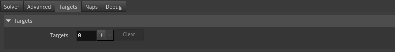
Go to the Targets tab in the AdnSkin parameters, add a new entry to Targets to add a geometry target (e.g., the glued muscles to simulate the fascia, the fat geometry to simulate the skin).
Provide the object path of the target geometry in Target World Mesh.
The AdnSkin is now ready to simulate using the default settings. Refer to the next section to customize its configuration.
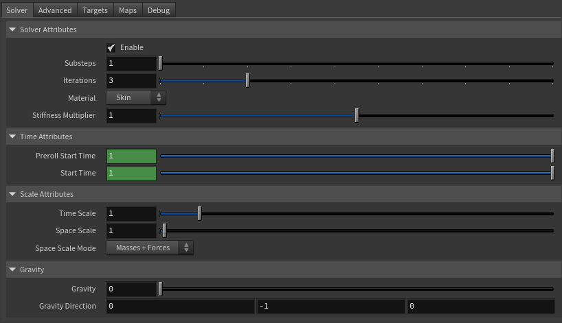
Flag to enable or disable the deformer computation.
Substeps
Integer
1
✓
Number of steps that the solver will execute per simulation frame. Greater values mean greater computational cost. Has a range of [1, 10]. The upper limit is soft, higher values can be used.
Iterations
Integer
3
✓
Number of iterations that the solver will execute per simulation step. Greater values mean greater computational cost. Has a range of [1, 10]. The upper limit is soft, higher values can be used.
Material
Enumerator
Skin
✓
Solver stiffness presets per material. The materials are listed from lowest to highest stiffness. There are 8 different presets: Fat: 103, Muscle: 5e3, Rubber: 106, Tendon: 5e7, Leather: 108, Wood: 6e9, Skin: 12e3.
Stiffness Multiplier
Float
1.0
✓
Multiplier factor to scale up or down the material stiffness. Has a range of [0.0, 2.0]. The upper limit is soft, higher values can be used.
Sets the scaling factor applied to the simulation time step. Has a range of [0.0, 2.0]. The upper limit is soft, higher values can be used.
Space Scale
Float
1.0
✓
Sets the scaling factor applied to the masses and/or the forces (e.g. gravity). AdonisFX interprets the scene units in centimeters. If modeling your creature you apply a scaling factor for whatever reason (e.g. to avoid precision issues in Houdini), you will have to adjust for this scaling factor using this attribute. If your character is supposed to be 170 units tall, but you prefer to model it to be 17 units tall, then you will need to set the space scale to a value of 10. This will ensure that your 17 units creature will simulate as if it was 170 units tall. Has a range of [0.0, 2.0]. The upper limit is soft, higher values can be used.
Space Scale Mode
Enumerator
Masses + Forces
✓
Determines if the spatial scaling affects the masses, the forces, or both. The available options are:
Masses: The Space Scale only affects masses.
Forces: The Space Scale only affects forces.
Masses + Forces: The Space Scale affects masses and forces.
Sets the magnitude of the gravity acceleration in m/s2. The value is internally converted to cm/s2. Has a range of [0.0, 100.0]. The upper limit is soft, higher values can be used.
Gravity Direction
Float3
{0.0, -1.0, 0.0}
✓
Sets the direction of the gravity acceleration. Vectors introduced do not need to be normalized, but they will get normalized internally.
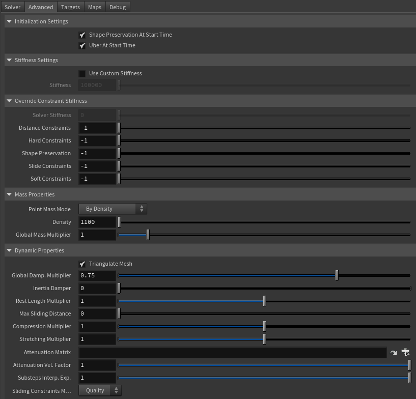
Flag that forces the shape preservation constraints to reinitialize at start time. This attribute has effect only if preroll start time is lower than start time.
Uber At Start Time
Boolean
True
✗
Flag that forces the uber constraints (hard, soft and slide) to reinitialize at start time. This attribute has effect only if preroll start time is lower than start time.
Stiffness Settings
Name
Type
Default
Animatable
Description
Use Custom Stiffness
Boolean
False
✓
Toggles the use of a custom stiffness value. If custom stiffness is used, Material and Stiffness Multiplier will be disabled and Stiffness will be used instead.
Stiffness
Float
105
✓
Sets the custom stiffness value. Its value must be greater than 0.0.
Override Constraint Stiffness
Name
Type
Default
Animatable
Description
Solver Stiffness
Float
0.0
✗
Shows the global stiffness value currently used by the solver.
Distance Constraints
Float
-1.0
✓
Sets the stiffness override value for distance constraints. If the value is less than 0.0, the global stiffness will be used. Otherwise, this custom stiffness will override the global stiffness. Has a range of [0.0, 1012]. The upper limit is soft, higher values can be used.
Hard Constraints
Float
-1.0
✓
Sets the stiffness override value for hard constraints. If the value is less than 0.0, the global stiffness will be used. Otherwise, this custom stiffness will override the global stiffness. Has a range of [0.0, 1012]. The upper limit is soft, higher values can be used.
Shape Preservation
Float
-1.0
✓
Sets the stiffness override value for shape preservation constraints. If the value is less than 0.0, the global stiffness will be used. Otherwise, this custom stiffness will override the global stiffness. Has a range of [0.0, 1012]. The upper limit is soft, higher values can be used.
Slide Constraints
Float
-1.0
✓
Sets the stiffness override value for slide constraints. If the value is less than 0.0, the global stiffness will be used. Otherwise, this custom stiffness will override the global stiffness. Has a range of [0.0, 1012]. The upper limit is soft, higher values can be used.
Soft Constraints
Float
-1.0
✓
Sets the stiffness override value for soft constraints. If the value is less than 0.0, the global stiffness will be used. Otherwise, this custom stiffness will override the global stiffness. Has a range of [0.0, 1012]. The upper limit is soft, higher values can be used.
NOTE
Providing a stiffness override value of 0.0 will disable the computation of that constraint.
Mass Properties
Name
Type
Default
Animatable
Description
Point Mass Mode
Enumerator
By Density
✓
Defines how masses should be used in the solver.
By Density allows to estimate the mass value by multiplying Density * Area.
By Uniform Value allows to set a uniform mass value.
Density
Float
1100.0
✓
Sets the density value in kg/m3 to be able to estimate mass values with By Density mode. The value is internally converted to g/cm3. Has a range of [0.001, 106]. Lower and upper limits are soft, lower and higher values can be used.
Global Mass Multiplier
Float
1.0
✓
Sets the scaling factor applied to the mass of every point. Has a range of [0.001, 10.0]. Lower and upper limits are soft, lower and higher values can be used.
Dynamic Properties
Name
Type
Default
Animatable
Description
Triangulate Mesh
Boolean
True
✗
Use the internally triangulated mesh to build constraints.
Global Damping Multiplier
Float
0.75
✓
Sets the scaling factor applied to the global damping of every point. Has a range of [0.0, 1.0]. The upper limit is soft, higher values can be used.
Inertia Damper
Float
0.0
✓
Sets the linear damping applied to the dynamics of every point. Has a range of [0.0, 1.0]. The upper limit is soft, higher values can be used.
Rest Length Multiplier
Float
1.0
✓
Sets the scaling factor applied to the edge lengths at rest. Has a range of [0.0, 2.0]. The upper limit is soft, higher values can be used.
Max Sliding Distance
Float
0.0
✗
Determines the size of the sliding area. It corresponds to the maximum distance to the closest point on the closest target mesh computed on initialization. The higher this value is, the higher quality and the lower performance. If the value provided is considered too high for a given target mesh, a warning will be displayed to the user. Has a range of [0.0, 10.0]. The upper limit is soft, higher values can be used.
Compression Multiplier
Float
1.0
✓
Sets the scaling factor applied to the compression resistance of every point. Has a range of [0.0, 2.0]. The upper limit is soft, higher values can be used.
Stretching Multiplier
Float
1.0
✓
Sets the scaling factor applied to the stretching resistance of every point. Has a range of [0.0, 2.0]. The upper limit is soft, higher values can be used.
Attenuation Matrix
String
✓
Object path of the node to extract the transformation matrix from to compute the velocity attenuation.
Attenuation Velocity Factor
Float
1.0
✓
Sets the weight of the attenuation applied to the velocities of the simulated vertices driven by the Attenuation Matrix. Has a range of [0.0, 1.0]. The upper limit is soft, higher values can be used.
Substeps Interp. Exp.
Float
1.0
✓
Sets the exponential factor to weight the interpolation at each substep. Has a range of [0.0, 1.0]. The upper limit is soft, higher values can be used. A value of 0.0 disables the interpolation: input geometry targets and attenuation matrix are not interpolated. A value of 1.0 applies linear interpolation (input geometry targets and attenuation matrix) between previous and current frame based on a linear weight, i.e. weight = substep / num_substeps. A value between 0.0 and 1.0 applies exponential interpolation (input geometry targets and attenuation matrix) between previous and current frame based on an exponential weight, i.e. weight = (substep / num_substeps) ^ exponent.
Sliding Constraints Mode
Enumerator
Quality
✓
Defines the mode of execution for the sliding constraints.
Quality is more accurate, recommended for final results.
Fast provides higher performance, recommended for preview.
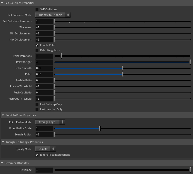
Self Collisions Properties
Name
Type
Default
Animatable
Description
Self Collisions
Boolean
False
✓
Toggles the self collisions on and off.
Self Collisions Mode
Enumerator
Triangle to Triangle
✓
Determines the method used for self-collision detection and response.
Point to Point: detects and resolves collisions between points only.
Triangle to Triangle: detects and resolves collisions between triangles, providing more accurate results for thin meshes but at a higher computational cost.
Self Collisions Iterations
Integer
1
✓
Sets the number of iterations for the self-collision correction. Has a range of [1, 10]. The upper limit is soft, higher values can be used.
Thickness
Float
-1.0
✓
Sets the thickness value for self-collision detection. Points closer than this distance will be considered in self-collision. A value of -1.0 disables thickness for self-collisions. Has a range of [-1.0, 3.0]. The upper limit is soft, higher values can be used.
Min Displacement
Float
-1.0
✓
Sets the minimum displacement a point must have to be considered for self-collision correction. Below this value, no correction will be applied. A value of -1.0 disables this check. Has a range of [-1.0, 1000.0]. The upper limit is soft, higher values can be used.
Max Displacement
Float
-1.0
✓
Sets the maximum displacement a point can have to be considered for self-collision correction. Above this value, no correction will be applied. A value of -1.0 disables this check. Has a range of [-1.0, 1000.0]. The upper limit is soft, higher values can be used.
Enable Relax
Boolean
True
✓
Toggles the relaxation process for self collision affected points.
Relax Neighbors
Boolean
False
✓
Sets if the relaxation process for self collisions should also consider the neighboring points that were detected in the self collision corrections.
Relax Iterations
Integer
1
✓
Sets the number of iterations to compute for self collision affected points. Smoothing and relaxation are applied in each iteration, while pushing in and pushing out are applied only in the last iteration. Has a range of [0, 20]. The upper limit is soft, higher values can be used.
Relax Weight
Float
1.0
✓
Influence of the smoothing and relaxation for self collision affected points. Has a range of [0.0, 1.0].
Relax Smooth
Float
0.5
✓
Amount of smoothing to apply for self collision affected points. Has a range of [0.0, 1.0].
Relax
Float
0.5
✓
Amount of relaxation to apply for self collision affected points. Has a range of [0.0, 1.0].
Push In Ratio
Float
0.0
✓
Amount of correction applied by the push in adjustment for self collision affected points. Has a range of [0.0, 2.0]. The upper limit is soft, higher values can be used.
Push In Threshold
Float
-1.0
✓
Maximum correction applied by the push in adjustment for self collision affected points. The threshold will be ignored if its value is 0.0 or less. Has a range of [-1.0, 2.0]. The upper limit is soft, higher values can be used.
Push Out Ratio
Float
0.0
✓
Amount of correction applied by the push out adjustment for self collision affected points. Has a range of [0.0, 2.0]. The upper limit is soft, higher values can be used.
Push Out Threshold
Float
-1.0
✓
Maximum correction applied by the push out adjustment for self collision affected points. The threshold will be ignored if its value is 0.0 or less. Has a range of [-1.0, 2.0]. The upper limit is soft, higher values can be used.
Last Substep Only
Boolean
False
✗
If enabled, self-collisions are only computed in the last substep of the simulation.
Last Iteration Only
Boolean
False
✗
If enabled, self-collisions are only computed in the last iteration of each substep.
Point Radius Mode
Enumerator
Average Edge
✗
Determines how the point radius is computed for self-collisions.
Uniform Value: uses the uniform value to estimate the radius.
Average Edge: uses the average edge length of the connected edges per vertex.
Minimum Edge: uses the minimum edge length of the connected edges per vertex.
Point Radius Scale
Float
1.0
✗
Sets the scaling factor applied to the point radius. It uses the value directly if the Point Radius Mode is set to Uniform Value. Has a range of [0.0, 3.0]. The upper limit is soft, higher values can be used.
Search Radius
Float
-1.0
✓
Sets the search radius for the self collision detection. It is used to determine the maximum distance to search for self collisions. If a value lower than 0.0 is used, the search radius will be estimated from the number of steps and the average edge length of the whole mesh. A value greater than 0.0 will represent a search radius in scene units. Has a range of [-1.0, 1.0]. The upper limit is soft, higher values can be used.
Quality Mode
Enumerator
Quality
✓
Sets the quality mode for self-collision detection.
Quality is more accurate, recommended for final results.
Fast provides higher performance, recommended for preview.
Ignore Rest Intersections
Boolean
True
✗
Ignore self-collision detection and correction for primitives that are intersecting in the rest pose.
Specifies the name of the per-point attribute to read the compression resistance values from. The expected attribute name is adnCompressionResistance. The expected range of the per-point values is [0.0, 1.0].
Global Damping Attribute
float
1.0
✗
Specifies the name of the per-point attribute to read the global damping from. The expected attribute name is adnGlobalDamping. The expected range of the per-point values is [0.0, 1.0].
Hard Constraints Attribute
float
1.0
✗
Specifies the name of the per-point attribute to read the hard weights from. The expected attribute name is adnHardConstraints. The expected range of the per-point values is [0.0, 1.0].
Mass Attribute
float
1.0
✗
Specifies the name of the per-point attribute to read the mass values from. The expected attribute name is adnMass. The expected range of the per-point values is [0.001, 1.0].
Self Collisions Point Radius Multiplier Attribute
float
1.0
✗
Specifies the name of the per-point attribute to read the point radius multiplier values from used by the self-collisions constraints in Point-To-Point mode to detect intersecting points. The expected attribute name is adnScPointRadiusMultiplier. The expected range of the per-point values is [0.001, 1.0].
Self Collisions Thickness Multiplier Attribute
float
1.0
✗
Specifies the name of the per-point attribute to read the thickness multiplier values from used by the self-collisions constraints to detect intersections. The expected attribute name is adnScThicknessMultiplier. The expected range of the per-point values is [0.001, 1.0].
Self Collisions Weights Attribute
float
1.0
✗
Specifies the name of the per-point attribute to read the self-collisions weights from to control the points that will be involved in self-collisions solving. The expected attribute name is adnScWeights. The expected range of the per-point values is [0.001, 1.0].
Shape Preservation Attribute
float
1.0
✗
Specifies the name of the per-point attribute to read the shape preservation values from. The expected attribute name is adnShapePreservation. The expected range of the per-point values is [0.0, 1.0].
Slide Constraints Attribute
float
1.0
✗
Specifies the name of the per-point attribute to read the sliding weights from. The expected attribute name is adnSlideConstraints. The expected range of the per-point values is [0.0, 1.0].
Max Sliding Distance Multiplier Attribute
float
1.0
✗
Specifies the name of the per-point attribute to read the maximum sliding distance multiplier from. The expected attribute name is adnMaxSlidingDistanceMultiplier. The expected range of the per-point values is [0.0, 1.0].
Soft Constraints Attribute
float
1.0
✗
Specifies the name of the per-point attribute to read the soft weights from. The expected attribute name is adnSoftConstraints. The expected range of the per-point values is [0.0, 1.0].
Stretching Resistance Attribute
float
1.0
✗
Specifies the name of the per-point attribute to read the stretching resistance values from. The expected attribute name is adnStretchingResistance. The expected range of the per-point values is [0.0, 1.0].
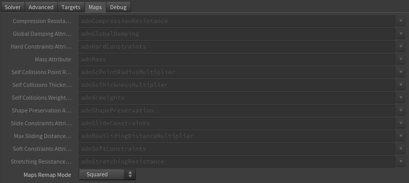
Maps Remap Mode
Enumerator
Squared
✗
Defines the mode of remapping the painted values of soft and shape preservation constraints. The other paintable maps remain unmodified. Each remap mode applies a function to the input painted values (x) to get the final value used for the simulation (y).
Linear: y = x
Squared: y = x^2
Cubic: y = x^3
Square Root: y = x^(1/2)
Cube Root: y = x^(1/3)
Logarithmic: y = log((exp(1) - 1) * x + 1)
NOTE
All maps parameters are disabled in the Maps tab because the attribute names are fixed to drive specific functionalities of the solver.
Fixed point attribute names also ensure compatibility with the API.
To copy the map names of the disabled attributes for painting (using an attribute paint node) right click on the disabled map attribute parameter, press "Copy Parameter", select the attribute paint node and on the attribute name entry right click and press "Paste Values". This allows to easily copy the attribute name for painting.
The Make Paintable utility provided in the AdonisFX menu > Utils, can be used to create the attribpaint node and automatically populate the entries with the map names of the AdnSkin SOP.
If a point attribute on the geostream does not match the naming convention exposed in the node, use an "Attribute Rename" node to rename the attribute to match the expected naming convention.
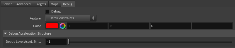
Enable or Disable the debug functionalities in the viewport for the AdnSkin deformer.
Feature
Enumerator
Hard Constraints
✓
A list of debuggable features for this deformer.
Distance Constraints: Draw Distance Constraint connections representing the constrained pair of vertices in the simulated mesh.
Hard Constraints: Draw Hard Constraints connections from the simulated mesh to the target mesh.
Self Collisions Volume: For each vertex draw a sphere whose volume depends on the point radius that the vertex has.
Shape Preservation: Draw Shape Preservation connections between the vertices adjacent to the vertices with this constraint.
Slide Constraints: Draw Slide Constraints connections from the simulated mesh to the target mesh.
Sliding Surface On Target: Draw outline of triangles covered by the Max Sliding Distance of each vertex.
Soft Constraints: Draw Soft Constraints connections from the simulated mesh to the target mesh.
Acceleration Structure: Draw a bounding box encapsulating all the collision primitives present in the internal acceleration structure used to solve self-collisions at the level specified in the attribute Debug Level Acceleration Structure. If the level set is -1, then all levels are displayed. If the value is greater than the number of levels, then no levels are displayed. Otherwise, only the specified level is displayed.
Rest Self Collisions: Draw the edges of the triangles that are intersecting with the mesh at rest.
Color
Color Picker
Red
✓
Selects the line color from a color wheel. Its saturation can be modified using the slider.
In order to provide more artistic control, some key parameters of the AdnSkin solver can be controlled via paintable point attributes. The maps are point attributes that must be present in the geometry stream injected into the SOP. For that, the Houdini attribpaint node can be used.
Name
Default
Description
Compression Resistance
1.0
Force to correct the edge lengths if the current length is smaller than the rest length. A higher value represents higher correction.
Tip: To optimize the painting of the weight, flood it to 1.0 as a starting point and tweak some areas later on.
Tip: Reducing the value of the weight in some areas will contribute to reduce wrinkling effect.
Global Damping
1.0
Set global damping per vertex in the simulated mesh. The greater the value per vertex is the more damping of velocities.
Hard Constraints
1.0
Weight to modulate the correction applied to the vertices to keep them at a constant transformation, local to the closest point on the closest target mesh at initialization. Hard Constraint maps will force the geometry points to keep the original position. A low value of Hard Constraints may be desired to allow the skin to create wrinkles and sliding effect.
Tip: In the example of a biped or quadruped creature, it is recommended to flood the geometry with a very low value 0.1, and then set a value of 1.0 to the edges of the skin to guarantee that it is properly attached to the target geometry.
Tip: Smooth the borders by using the Smooth and Flood combination to make sure that there are no discontinuities in the weights map. This will help the simulation to not produce sharp differences in the dynamics of every vertex compared to its connected vertices.
Masses
1.0
Set individual mass values per vertex in the simulated mesh.
Self Collision Point Radius Multiplier
1.0
Multiply the point radius of each vertex.
Tip: Paint with a value of 0.0 the areas that should not compute self collisions to reduce the computational impact.
Self Collision Thickness Multiplier
1.0
Multiply the Thickness of each vertex.
Tip: Paint with a value of 0.0 the areas to ignore the thickness for the intersections detection process; and with a value greater than 0.0 the areas to push along the direction of the normals for the intersections detection process.
Self Collision Weights
1.0
Amount of correction to apply to the current vertex when a collision with another vertex is detected.
Tip: Paint with a value of 0.0 the areas that should not compute self collisions to reduce the computational impact.
Tip: Paint with a higher value the areas that should receive more correction due to self-intersections, and with a lower value the areas that should receive less correction.
Shape Preservation
1.0
Amount of correction to apply to the current vertex to maintain the initial state of the shape formed with the surrounding vertices.
Slide Constraints
0.0
Weight to modulate the correction applied to the vertices to keep them at a constant distance to the target mesh sliding along the target surface.
Tip: In the example of a biped or quadruped creature, it is recommended to set a value of 1.0 on the scapulas, shoulders, elbows and knees and an overall value of 0 on the rest of the body.
Tip: Smooth the borders by using the Smooth and Flood combination to make sure that there are no discontinuities in the weights map. This will help the simulation to not produce sharp differences in the dynamics of every vertex compared to its connected vertices.
Max Sliding Distance Multiplier
1.0
Determines the size of the sliding area per vertex. It corresponds to the maximum distance to the closest point on the closest target mesh computed on initialization. Greater values will allow for larger sliding areas but will also increase the computational cost.
Tip: For areas where sliding is not required paint to 0. Use values closer to 1 in areas where more sliding freedom should be prioritized.
Soft Constraints
0.0
Weight to modulate the correction applied to the vertices to keep them at a constant distance to the closest point on the closest target mesh at initialization. Painting these constraint weights would allow the deformer to create a wrinkle effect when combined with hard and slide weights.
Tip: In the example of a biped or quadruped creature, it is recommended to flood the geometry with a low value 0.2.
Stretching Resistance
1.0
Force to correct the edge lengths if the current length is greater than the rest length. A higher value represents higher correction.
Tip: To optimize the painting of the weight, flood it to 1.0 as a starting point and tweak some areas later on.
Tip: Smooth the borders by using the Smooth and Flood combination to make sure that there are no discontinuities in the weights map. This will help the simulation to not produce sharp differences in the dynamics of every vertex compared to its connected vertices.
NOTE
To tweak the point attributes of an AdnSkin SOP, an attribpaint is needed. To ease the creation and initial configuration of this node, select the AdnSkin SOP and click on AdonisFX > Utils > Make Paintable. This utility will create an attribcreate node to define the required point attributes and assign their default values followed by an attribpaint node to allow these attributes to be modified. Both nodes are automatically named and properly connected to the AdnSkin node.
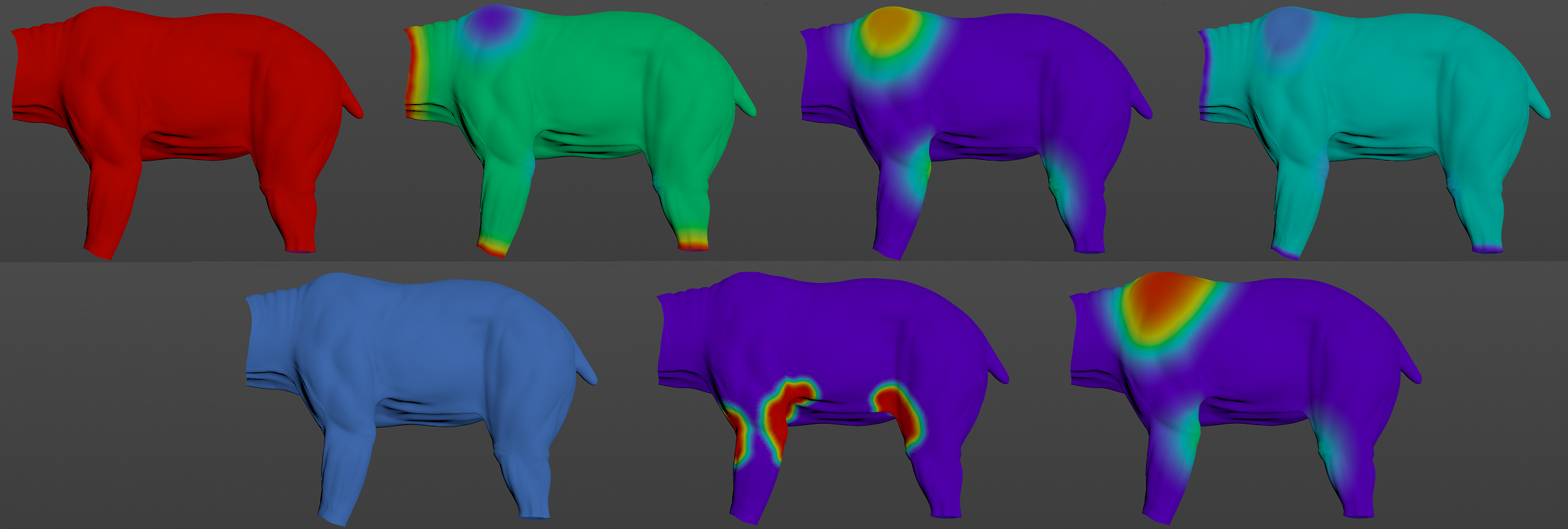
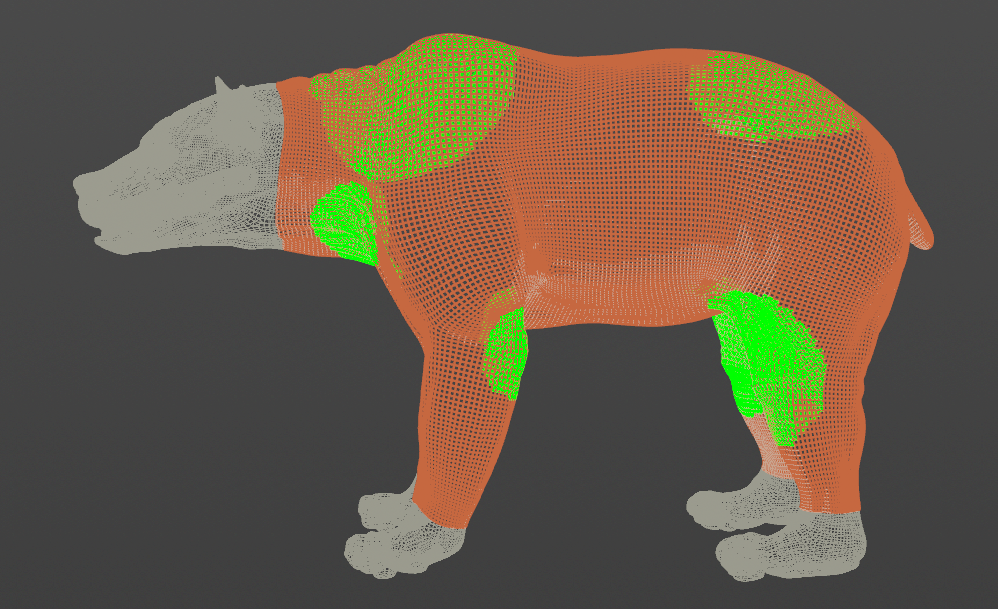
Figure 7: Example of painted weights on the skin of a bear character. First row, from left to right: maps flooded to 1.0 (which correspond to compression, stretching, masses, global damping, self collision radius and thickness multiplier), hard constraints, slide constraints and soft constraints. Second row, from left to right: shape preservation, self collision weights and max sliding distance multiplier.
NOTE
Hard, Soft and Slide values are normalized to ensure that the sum of the three values for each vertex is in the range [0.0, 1.0].
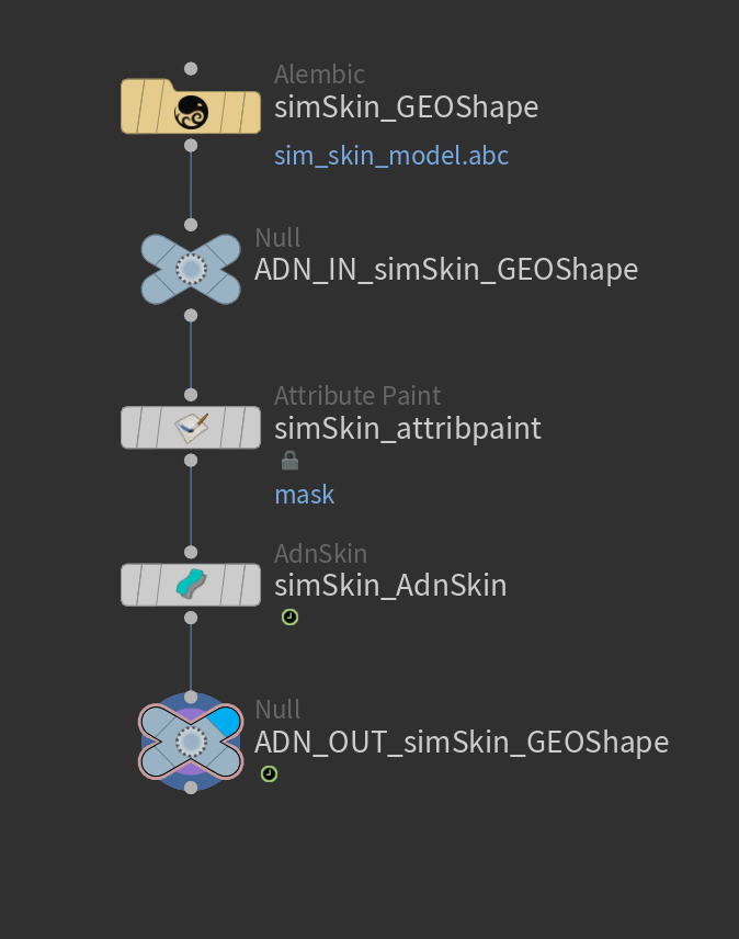
Figure 8: Example of AdnSkin network. Using null nodes with ADN_IN_ and ADN_OUT_ prefixes to encapsulate the AdonisFX deformable section is recommended to keep the network compatible with the API.
In order to better visualize deformer constraints and attributes in the Houdini viewport there is the option to enable the debugger, found in the switcher menu labeled Debug in the parameter interface. The visualization of the guide geometry is only activated when selecting the node to debug and cannot be enabled globally.
To enable the debugger the Debug checkbox must be marked. To select the specific feature you would like to visualize, choose it from the list provided in Features. The features that can be visualized with the debugger in the AdnSkin deformer are:
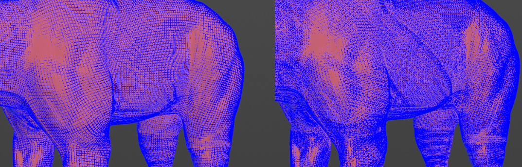
Distance Constraints: For each pair of vertices forming a constraint a line will be drawn. If the Triangulate Mesh option is disabled the debugged lines will align with the edges of the mesh polygons. If the Triangulate Mesh option is enabled the debugged lines will align with the edges of the underlying triangulation of the mesh.
Hard Constraints: For each vertex, a line will be drawn from the simulated mesh vertex to the corresponding point on the target mesh if its Hard Constraints weight is greater than 0.0.
Self Collisions Volume: For each vertex, a sphere will be drawn representing the volume that will collide if its Self Collision Point Radius Multiplier weight and the Point Radius Scale are greater than 0.0.
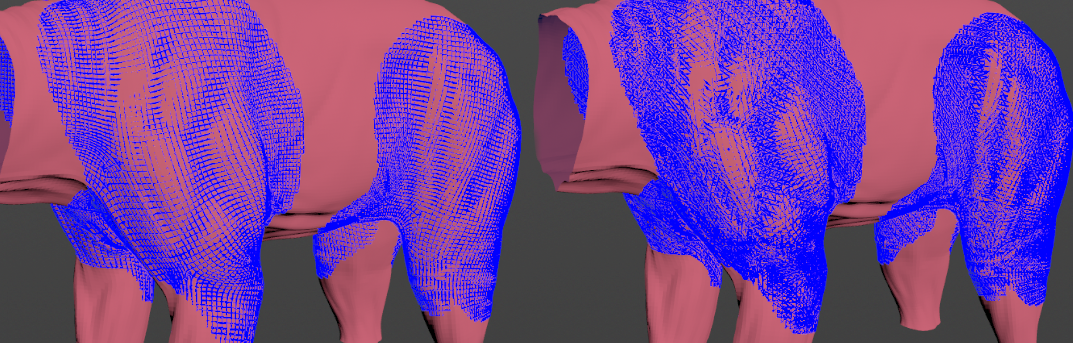
Shape Preservation: For each vertex with a shape preservation weight greater than 0.0, a line will be drawn from each adjacent vertex to the opposite adjacent vertex.
Slide Constraints: For each vertex, a line will be drawn from the simulated mesh vertex to the corresponding point on the target mesh if its Slide Constraints weight is greater than 0.0.
Sliding Surface On Target: For each vertex, lines will outline the target triangles within the reach of its Max Sliding Distance.
Soft Constraints: For each vertex, a line will be drawn from the simulated mesh vertex to the corresponding point on the target mesh if its Soft Constraints weight is greater than 0.0.
Acceleration Structure: For each level in the acceleration structure used to solve self-collisions, display a box representing the bounding box encapsulating all the collision primitives in that level. If the value of Debug Level Acceleration Structure is -1, then all levels are displayed. Otherwise, only the specified level is displayed. If the value is greater than the number of levels, then no levels are displayed.
Rest Self Collisions: For each triangle intersecting with the mesh at rest, the 3 edges of the triangle are displayed.
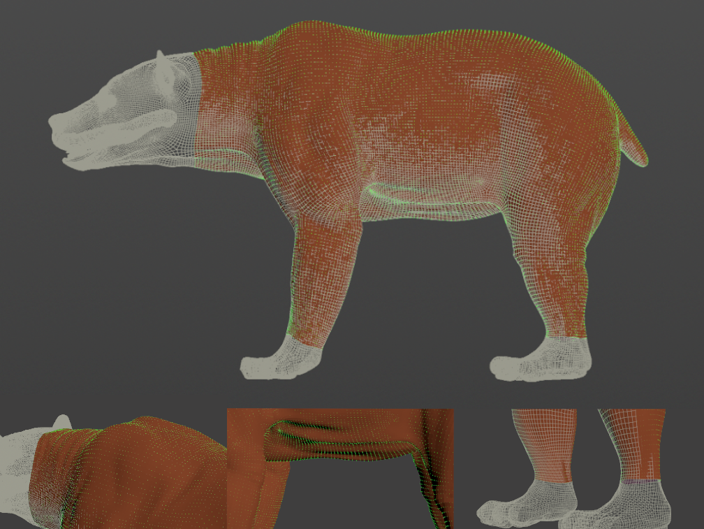
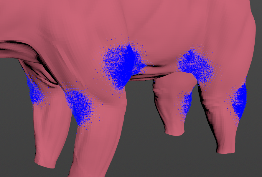
Figure 9: Displaying the target and simulated mesh. Debugger enabled displaying a test example with Soft Constraints colored in green.Figure 10: Displaying the target and simulated mesh. Debugger enabled displaying the Sliding Surface colored in green.Figure 11: Displaying the simulated mesh. Debugger enabled displaying the Distance Constraints colored in blue with Triangulate Mesh option disabled (Left) and enabled (Right).Figure 12: Displaying the simulated mesh. Debugger enabled displaying the Shape Preservation Constraints colored in blue with Triangulate Mesh option disabled (Left) and enabled (Right).Figure 13: Displaying the simulated mesh. Debugger enabled displaying the Self Collisions Volume colored in blue.
NOTE
The width of the debug lines can be modified from the global viewport settings in Houdini.
For better contrast while debugging, enable the Dark background option in the viewport settings.
Connections in AdonisFX for Houdini should be handled in two ways:
Detail expression: detail("/obj/geo1/L_adnLocatorRotation_armFlexionShape", "adnActivationRotation", 0) where the first component should contain an API compliant naming convention and the second the detail attribute name that some of the AdonisFX SOP nodes output. This should be used when the requirement is for the connected geometry to cook before retrieving the detail attribute. This could be used for example to drive a parameter of the node using the activation value output from a sensor/locator.
Channel expression: ch("../AdnMuscle1/envelope") where the first component should contain an API compliant naming convention and the second the referenced channel to the parameter name. This could be used to for example connect a float attribute to drive a parameter on the node.

 SOP type.